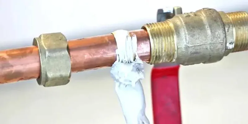
Compression fittings, also called ferrule-type or flareless tube fittings, are used on instrument lines, sample lines, gas panels, and hydraulic and process tubing. They need no welding and can be taken apart and remade. They are also a classic source of small, stubborn leaks. When a stainless steel tube leaks at one, the fitting is often blamed first.
In many cases the cause is on the tube side: the tube is too hard, slightly oval, scratched, the wrong wall thickness, or carrying a weld bead. In other cases the tube is fine and the installation was not. This guide explains how a compression fitting seals, which material and dimensional checks matter most, how to diagnose a leak, and how to specify tubing that seals reliably.
A compression fitting seals on the outside surface of the tube, so the tube has to be softer than the fitting, round, correctly sized, smooth, and free of scratches, burrs, and weld beads. For stainless steel, one major fitting manufacturer limits tubing hardness to 90 HRB (200 HV) and calls for fully annealed, seamless or welded-and-drawn tube. ASTM A269 allows an OD tolerance of ±0.005 in. and ovality up to twice that tolerance, which can be too loose for precision fittings. If the tube is good, check installation: tube bottomed on the shoulder, correct turns of the nut, no mixed parts, and clean, undamaged ferrules.
Why Do Stainless Steel Tubes Leak at Compression Fittings?
Leaks come from three places: the tube (too hard, out of size or round, scratched, wrong wall, weld bead), the installation (tube not bottomed, wrong tightening, mixed or reused parts, dirt), and the service conditions (vibration, thermal cycling, corrosion). The tube side is the most often overlooked.
Fitting manufacturers report that installation and preparation errors are common. One manufacturer's field guidance states that poor or angled cutting, incomplete deburring, and contaminated tube ends are among the most common root causes of leaks, and cites regulatory inspections of small-bore tubing systems that found around one in four inspected fittings contained faults such as incorrect installation, under-tightening, or mismatched components. Another industry article describes under-tightening of tube fittings, especially in harder materials such as stainless steel, as a major cause of leakage.
|
Cause Family |
Examples |
How to Check |
|
Tube material |
Tube too hard or not fully annealed; wrong alloy for the fitting |
Mill certificate; hardness test |
|
Tube dimensions |
OD undersize or oversize; ovality; wrong or uneven wall thickness |
Micrometer, caliper, wall measurement |
|
Tube surface and ends |
Scratches, dents, burrs, weld bead, angled or dirty cut |
Visual and tactile inspection under light |
|
Installation |
Tube not bottomed; under- or over-tightening; mixed components; reused ferrules |
Gap gauge, scribe mark, parts inspection |
|
Service |
Vibration, thermal cycling, pressure spikes, corrosion near fittings |
Support spacing, cycling tests, corrosion inspection |
Table 1. Cause families behind leaks at stainless steel compression fittings.
How Does a Compression Fitting Seal on a Stainless Steel Tube?
A two-ferrule compression fitting seals by squeezing metal ferrules onto the outside of the tube as the nut is tightened. The front ferrule makes the seal; the back ferrule grips the tube. Because the seal is on the tube's outer surface, the tube's hardness, shape, and surface finish control whether it holds.
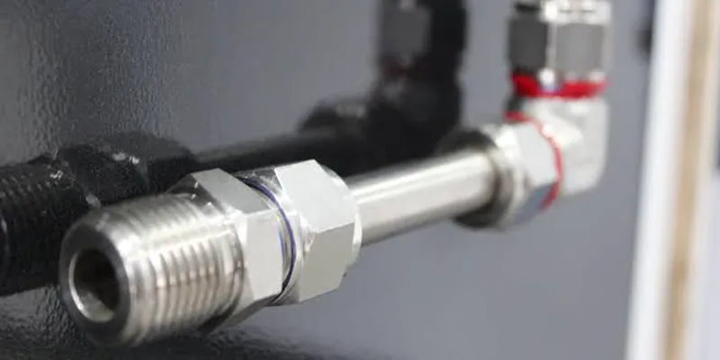
When the nut is tightened, the ferrules are driven against a tapered seat in the fitting body and are forced onto the tube. This permanently "swages" the ferrules onto the tube so that metal contacts metal around the full circumference. For this to work, the tube must be softer than the ferrule and fitting material so that the ferrules can bite and shape the surface. It must also be round enough to enter the fitting and smooth enough that no leak path is left under the ferrule.
Manufacturers explain the surface point directly: because the fitting seals on the tube outside diameter, system fluid can leak through even a minute path, and some surface defects can provide that path. A heavy-wall tube resists ferrule action more than a thin-wall tube, which lets the ferrules coin out minor surface imperfections; this is one reason wall thickness matters. The probability of a scratch grows with tube diameter.
Is Tube Hardness a Common Cause of Leaks?
Yes. If the tube is too hard, the ferrules cannot bite and seal properly. One major manufacturer states that its stainless steel tube fittings have been repeatedly tested successfully with tubing up to 200 HV or 90 HRB, and requires fully annealed tubing.
The basic rule of ferrule-type fittings is that the tubing must be softer than the fitting material. Hard tubing can come from unannealed or cold-drawn material, or from severe bending or work hardening, because austenitic stainless steel hardens quickly when cold worked. Tubing with a higher hardness than the fitting may not swage correctly, so the joint can look tight but weep or lose grip. Hardness limits depend on the alloy and the fitting manufacturer.
|
Tubing Material (fully annealed, seamless) |
Maximum Hardness (one manufacturer's published limit) |
Notes |
|
Soft annealed carbon steel (for example ASTM A179) |
72 HRB or 130 HV |
Reference point |
|
316/316L and similar austenitic stainless (ASTM A269 or A213) |
90 HRB or 200 HV |
Seamless, or welded and drawn |
|
Alloy 400 (ASTM B165) |
75 HRB |
Nickel-copper alloy |
|
Alloy 20 |
95 HRB |
Annealed seamless or welded and drawn |
|
Alloy 625 (ASTM B444) |
25 HRC (about 266 HV) |
Nickel alloy |
|
Alloy 2507 super duplex (ASTM A789) |
32 HRC |
Duplex stainless |
Table 2. Maximum tubing hardness published by one fitting manufacturer for its tube fittings. Other manufacturers and fitting designs have their own limits; follow the data for your fitting.
Hardness is easy to check and often skipped. Ask for hardness on the mill test certificate, and test a sample of delivered tubing, especially if it has been bent, straightened, or re-drawn. Note that the same alloy in the annealed and in the cold-worked condition can differ by many Rockwell points.
Which Dimensional Checks Matter Most for Compression Fittings?
Check outside diameter, ovality, wall thickness and its uniformity (concentricity), end squareness, and burrs. Order tubing to outside diameter and wall thickness, not to inside diameter.
|
Check |
Why It Matters |
Requirement or Practice |
|
Outside diameter |
The ferrule must grip and seal on the OD |
ASTM A269 allows ±0.005 in. (±0.13 mm) for common instrumentation sizes; one manufacturer specifies tighter limits (for example ±0.003 in.) in its tubing tables |
|
Ovality |
Oval tube may not enter the fitting or seal around the full circumference |
A269 allows ovality up to twice the OD tolerance; the manufacturer notes such tubing may not fit precision fittings |
|
Wall thickness |
Too thin collapses under the ferrule; too thick can resist swaging |
Check against the fitting maker's minimum and maximum wall for each OD and pressure |
|
Concentricity |
Wall that is thick on one side and thin on the other seals unevenly |
Wall thickness should be consistent all the way around |
|
Order basis |
Controlling ID can change OD and wall tolerance |
Order to OD and wall thickness only, not ID or average wall |
|
Ends |
Angled or burred ends scratch the OD and seat badly |
Cut square; deburr inside and outside; avoid chips from hacksaw cutting |
Table 3. Dimensional checks for tubing used with compression fittings.
How Do OD Tolerance and Ovality Lead to Leaks?
Undersize tube lets the ferrule grip unevenly and leaves a gap; oversize or oval tube resists entry and can scratch the OD or damage the ferrule as it is forced in. Because A269 permits ovality of twice the OD tolerance, tubing that meets the standard can still be a poor fit for a precision fitting.
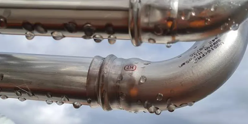
A simple calculation shows why. For a 1/4-inch tube with an OD tolerance of ±0.005 in., ASTM A269 allows ovality up to 0.010 in. As a fraction of the 0.250 in. diameter, that is 4%. A tube measuring 0.255 in. in one direction and 0.245 in. in the other still meets the standard, but the large dimension can be too big for the fitting bore while the small dimension leaves a clearance the ferrule must close. Manufacturers warn that oval tube should not be forced into a fitting, because the force can damage ferrules, nuts, and bodies.
This is why many users specify tighter OD and ovality limits for tubing used with compression fittings, and why tubing that is good for general service may not be good for instrumentation. For a broader treatment of how to measure ovality and what causes it, see our companion articles on stainless steel pipe ovality and on pipe end distortion; the same measurement principles apply to tube.
Do Scratches, Burrs, and Weld Seams on the Tube Cause Leaks?
Yes. Because the seal is on the tube OD, any scratch, dent, raised area, burr, or external weld bead can become a leak path. Use seamless tubing or welded-and-drawn tubing, and inspect the OD before assembly.
Manufacturers state that tubing with a depression, scratch, raised portion, or other surface defect will be difficult to seal and should never be forced into the fitting. Scratches can occur if an OD burr is left on the tube after cutting, or from dragging tube across hard surfaces. Longitudinal scratches (along the tube length) are the most damaging because they run across the ferrule seal.
Welded tubing needs special attention. Tubing used with these fittings should be seamless or welded and drawn, meaning the weld has been cold-drawn smooth so the OD is uniform. If you can see a weld bead on the OD, the manufacturer's tubing checklist warns it may create problems. Welded tubing should also be checked for corrosion or pitting along the weld. Scratches are not only a sealing issue; in chloride environments they can become sites for crevice or pitting corrosion near the fitting, which can produce weeping leaks later.
|
Surface Condition |
Effect on Seal |
Action |
|
Longitudinal scratch |
Direct leak path under the ferrule |
Cut the tube back past the scratch and re-install |
|
OD burr from cutting |
Scratches the ferrule seat and tube as it is inserted |
Deburr; use a proper tube cutter or saw; avoid hacksaw chips |
|
Dent or flat from handling |
Prevents uniform ferrule contact |
Cut off the damaged section |
|
External weld bead |
Raised area interrupts the seal |
Use seamless or welded-and-drawn tubing |
|
Dirt or grit on tube or ferrule |
Embeds under the ferrule and scratches |
Clean; keep tube ends capped until use |
Table 4. Tube surface conditions and their effect on compression fitting seals.
How Does Wall Thickness Affect Sealing?
Wall thickness must be within the fitting maker's limits for the tube OD. Thin-wall tube can collapse under the ferrules unless supported, while heavy-wall tube resists the ferrule action but copes better with minor surface defects.
Manufacturers advise checking extremes of wall thickness against their minimum and maximum wall limits. Thin-wall tube offers less resistance and is more likely to crush or deform as the ferrules close, which can leave a leak path or reduce grip, and tube inserts are often used in such cases per the manufacturer's data. Heavy-wall tube resists ferrule action more, which can help seal minor surface imperfections but can also require more careful installation. In both cases, wall thickness also determines the pressure rating of the tube itself, so the wall must suit the working pressure as well as the fitting.
Concentricity matters as well. A tube with a thick wall on one side and a thin wall on the other can seal unevenly. Check wall thickness at several points around the circumference, not just one.
What Installation Errors Cause Leaks Even When the Tube Is Good?
The most common errors are the tube not fully bottomed on the fitting shoulder, under-tightening (or over-tightening), mixing components from different manufacturers, reusing damaged ferrules, and dirt or galling. Follow the manufacturer's turn count and use a gap gauge on initial installation.
|
Error |
What Happens |
Correct Practice (typical for a two-ferrule design) |
|
Tube not bottomed on the shoulder |
Ferrules set in the wrong position; weak seal and grip |
Insert tube until it rests firmly on the shoulder before tightening |
|
Under-tightening |
Ferrules not fully swaged; leak or tube ejection under pressure |
Tighten the nut 1¼ turns from finger-tight (3/4 turn for 1/16, 1/8, 3/16 in. and 2, 3, 4 mm sizes); verify with a gap inspection gauge on initial installation |
|
Over-tightening |
Tube collapse, ferrule damage, thread galling |
Use the specified turns, not feel; hold the body with a back-up wrench |
|
Mixed components |
Ferrule and seat geometries are not standardized across brands; latent leaks after thermal cycling or vibration |
Never mix tube, ferrules, nuts, and bodies from different manufacturers |
|
Reassembly done like a first pull-up |
Over-swaged or damaged ferrules |
On reassembly, insert the tube with pre-swaged ferrules, tighten to the previous position, then about 1/4 turn more; do not use the gap gauge on reassembled fittings |
|
Dirt, damaged seat, or galled threads |
Leak path or seized nut |
Inspect parts before assembly; use manufacturer-approved lubricant where permitted |
Table 5. Installation errors and correct practice. Turn counts shown are from one manufacturer's published instructions; follow the instructions for your fitting.
Visual inspection alone is not enough to confirm a leak-tight fitting, because there is no way to see whether a fitting was previously tightened correctly or remade outside tolerance. This is why gap gauges and consistent procedures matter. Always depressurize the system before disassembling or tightening a fitting.
What Service Conditions Cause Compression Fittings to Leak Later?
Vibration, thermal cycling, pressure spikes, long unsupported tube runs, and corrosion near fittings cause leaks that appear after a joint has passed its initial test.
Routing that ignores vibration, access, or thermal expansion, combined with inadequate support, is a common cause of fatigue failures and leaks over the long term. Long unsupported spans under vibration shorten tube life. Mixed or marginal assemblies can look tight but seal unpredictably under temperature cycling.
Stainless steel in chloride environments, such as coastal or washdown areas, can also develop pitting or crevice corrosion at scratched areas near fittings. Good practice is to support tubing close to fittings, allow for thermal movement, keep the OD clean and undamaged, and leak test after thermal cycling when the application demands it.
How Do You Diagnose a Leaking Compression Fitting?
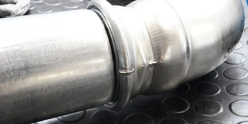
Work from the location of the leak: leak at the body seal usually means a scratched tube or dirt on the seat; leak at the nut threads suggests galling or mixed parts; and leak that appears after cycling suggests incomplete swaging, mixed components, or vibration.
|
Observation |
Likely Cause |
Action |
|
Leak at tube-to-body seal |
Scratched or dented tube; dirt on seat; tube not bottomed |
Depressurize; cut back the tube; clean the seat; reinstall |
|
Leak at nut threads |
Galled threads or mixed components |
Replace the fitting; use proper lubricant where permitted |
|
Leak after thermal cycling or vibration |
Marginal swage, mixed parts, unsupported tube |
Check turn count and parts; add supports; remake with matched components |
|
Tube pulls out or moves |
Under-tightening or hard/oversize tube |
Check hardness and OD; reinstall with correct pull-up |
|
Leak returns after retightening |
Damaged ferrules or oval tube |
Replace ferrules or cut back; measure OD and ovality |
Table 6. Leak diagnosis guide for compression fittings.
How Should You Specify and Inspect Stainless Tubing for Compression Fittings?
Specify fully annealed, seamless or welded-and-drawn tubing to ASTM A269 or A213, with hardness at or below the fitting maker's limit, OD and ovality limits tighter than the standard if needed, wall tolerance, scratch-free surface, square deburred ends, and capped and clean packing. Verify on receipt and run a pilot assembly.
|
Item |
What to Specify or Check |
|
Standard and product form |
ASTM A269 or A213 (general requirements per ASTM A1016); seamless or welded and drawn; no visible external weld bead |
|
Condition and hardness |
Fully annealed; hardness at or below the fitting manufacturer's limit (for example 90 HRB or 200 HV for 316 stainless in one manufacturer's data); hardness reported on the mill certificate |
|
Diameter and ovality |
State OD tolerance and maximum ovality (for example, tighter than A269's ±0.005 in. and 2× ovality if the fitting requires it); measure with micrometer or calipers at several angles |
|
Wall thickness |
Wall within the fitting maker's limits for the OD and working pressure; check concentricity |
|
Surface |
Free of scratches, dents, and raised areas on the OD; smooth bore; no burrs |
|
Ends and cutting |
Square, deburred; cut with proper tube cutter or saw; keep stainless-only tools |
|
Cleanliness and packing |
Caps on both ends; protective packing; storage separate from carbon steel; handle to avoid OD scratches |
|
Traceability |
Heat numbers on tube and certificate; EN 10204 3.1 certificate where required |
|
Qualification |
Make a pilot assembly with your actual tubing and fittings; leak test after thermal cycling and under expected vibration |
Table 7. Specification and inspection checklist for tubing used with compression fittings.
Frequently Asked Questions
Why does my stainless steel tubing leak at a compression fitting?
The most common causes are tube that is too hard, oval, or scratched; tube not bottomed on the fitting shoulder; under-tightening; and mixed or reused parts. Check the tube first, then the installation.
How hard can stainless steel tubing be for compression fittings?
One major manufacturer states its stainless steel tube fittings have been tested successfully with tubing up to 90 HRB (200 HV) and requires fully annealed tubing. Other manufacturers may differ, so follow the fitting maker's data.
Does ovality cause leaks?
It can. ASTM A269 allows ovality of twice the OD tolerance, and the manufacturer notes such tubing may not fit precision tube fittings. Do not force oval tube into a fitting.
Can I use welded stainless tubing with compression fittings?
Use welded-and-drawn tubing, or seamless, so there is no raised weld bead on the OD. A visible bead on the OD can interrupt the ferrule seal.
How many turns should I tighten a compression fitting?
For one manufacturer's two-ferrule fittings, 1¼ turns from finger-tight (3/4 turn for 1/16, 1/8, 3/16 in. and 2, 3, 4 mm sizes) on initial installation, verified with a gap inspection gauge. Reassembly uses a different procedure. Always follow your fitting maker's instructions.