|
Topic |
Fact |
|
Core principle |
A surface reading describes the skin. A heavy duplex section is accepted or rejected by its slowest-cooling region. |
|
Standard-backed rule |
ASTM A923 instructs the user to test the region most likely to form intermetallic phase and names the slowest-cooling location as that region. |
|
Explicit warning in the standard |
ASTM A923 states that meeting a product specification's chemical and mechanical requirements does not necessarily mean harmful intermetallic phases are absent. |
|
Producer evidence |
Outokumpu reports ferrite scope surface readings on rolled products can be up to 20 percent below the true ferrite content, and that the response varies with the cross-section measured. |
|
PMI blind spot |
Handheld XRF cannot determine carbon or nitrogen and reads only a few micrometres to a few tens of micrometres into steel. |
|
Why nitrogen matters |
Nitrogen is an intentional austenite-forming addition in duplex grades and helps set the ferrite-to-austenite balance and the rate of austenite formation on cooling. |
|
Temperature window |
Detrimental intermetallic phases form across roughly 320 to 955 degrees Celsius per ASTM A923, with sigma and chi precipitation commonly concentrated around 600 to 1000 degrees Celsius. |
|
Grade comparison |
2507 offers higher strength and PREN but precipitates faster than 2205, so it is less forgiving in a heavy section. |
|
Specimen location |
Mechanical specimens are normally taken at quarter-thickness or midway between surface and centre; metallography is performed on a polished cross-section. |
|
NDT boundary |
Ultrasonic testing and radiography find discontinuities, not intermetallic phases. |
|
Commercial logic |
Through-thickness verification is a small planned cost; a rejected machined heavy forging is a large unplanned one. |

This brief compares what a fast surface measurement can tell you about a duplex stainless steel heavy section with what the rest of the section may actually be doing. It is written for buyers, inspectors and engineers who have to decide whether a certificate is enough evidence to release a thick plate, a large forging, a heavy-wall fitting or a casting for chloride or sour service.
On a heavy duplex section, a passing surface reading is screening evidence, not release evidence. The part is only as good as its slowest-cooling, slowest-heating, least accessible region, and every acceptance test has to be placed there on purpose.
Duplex stainless steels are used because a roughly balanced ferrite-austenite microstructure delivers high strength, strong resistance to chloride stress corrosion cracking, and useful pitting resistance at a lower alloy cost than nickel-based alternatives. That balance is created by chemistry and then frozen in place by solution annealing followed by a rapid quench. It is therefore a product of thermal history, not just of a grade name on a certificate.
Thickness changes thermal history. The surface quenches first; the centre quenches last. A handheld spectrometer, a ferrite scope, a hardness tester or a surface thermocouple can all be perfectly calibrated and can still describe only the region they touched. The argument in this brief is not that those tools are wrong. It is that they answer a different question from the one the buyer is asking.
Practical note: How to read this brief: each section opens with a one-sentence conclusion, followed by the reasoning and, where useful, a comparison table. Every table is captioned and self-contained so that a single answer can be extracted and cited without the surrounding text.
What Does a Surface Reading Actually Measure on a Duplex Heavy Section?
A surface reading measures the skin of the component, not the component. On a duplex stainless steel heavy section, that distinction matters because the properties that justify buying duplex live in the microstructure, and the microstructure is not guaranteed to be the same at the centre as it is at the surface.
A duplex grade earns its reputation from a roughly balanced mixture of ferrite and austenite, plus a controlled nitrogen content. None of those three things is evenly distributed by default. The skin is the first part to heat, the first part to cool, and the only part that most handheld instruments can reach. The centre heats last, cools slowest, and is where centreline segregation and slow-cooling precipitates collect.
Think of a thick loaf of bread taken out of an oven. The crust is dry and firm within minutes; the middle is still warm and damp an hour later. A probe pressed into the crust tells you the crust is done. It says nothing reliable about the middle. A 100 mm duplex plate or a 200 mm duplex forging behaves the same way, except that the property at stake is toughness and pitting resistance rather than moisture.
This is not an argument against surface testing. Surface readings are fast, non-destructive, cheap, and excellent at catching a mixed grade or a badly out-of-range surface. The argument is about what a surface reading is allowed to conclude. It can conclude that the surface passed. It cannot, on its own, conclude that the section passed.
Table 1. What common surface readings actually probe, and what they cannot see
|
Reading |
What the instrument probes |
Approximate information depth |
What it cannot tell you |
|
Handheld XRF / PMI |
Elemental chemistry of a thin surface layer |
A few micrometres to a few tens of micrometres in steel |
Carbon, nitrogen, centre chemistry, phase balance, heat-treatment condition |
|
Magnetic ferrite scope |
Magnetic permeability of the near-surface layer |
Surface and near-surface; strongly product- and thickness-dependent |
Core phase balance, sigma or chi phase, through-thickness gradient |
|
Brinell or Rockwell hardness |
Resistance to indentation at the surface |
Roughly tenths of a millimetre to about a millimetre, depending on scale and load |
Small intermetallic fractions, core impact toughness, pitting resistance |
|
Surface thermocouple or pyrometer |
Temperature of the exposed face |
The face only |
Whether the centre reached the solution-annealing temperature, or how long it stayed there |
|
Visual and liquid-penetrant examination |
Surface-breaking discontinuities |
Open surface |
Subsurface defects and all microstructural condition |
|
Ultrasonic thickness or flaw detection |
Acoustic reflections through the whole thickness |
The full section |
Phase balance and intermetallic precipitates; ultrasound finds discontinuities, not phases |
Working definition: a heavy section is any product thick enough that the centre and the surface experience meaningfully different heating and cooling rates. In duplex practice this usually starts becoming a purchasing concern above roughly 25 to 50 mm, and becomes a governing concern for large forgings, thick tube sheets, heavy-wall fittings and castings.
Why Does Thickness Change Whether a Surface Reading Is Representative?
Thickness changes the cooling rate at the centre, and cooling rate controls the duplex microstructure. Below about 12 mm the whole section responds almost together; above roughly 50 mm the surface and the centre can follow two different thermal histories in the same heat-treatment cycle.
Heat leaves a steel part through its surface. The further a point is from that surface, the longer it takes to lose heat, because the steel between that point and the quench water acts as insulation. Water quenching a thin sheet pulls the entire thickness through the dangerous 600 to 1000 degrees Celsius precipitation window quickly. Water quenching a 100 mm plate cannot pull the mid-thickness through equally quickly, no matter how vigorously the tank is agitated.
ASTM A923 states that duplex stainless steels can form intermetallic compounds when exposed in the range of approximately 320 to 955 degrees Celsius, and that the rate of these precipitation reactions depends on the composition and the thermal or thermomechanical history of each individual piece. The standard's own wording is the clearest possible statement of why thickness matters: the history of the skin and the history of the centre are not the same history.
The second effect is time at temperature on the way up. A furnace thermocouple or a load-surface pyrometer records the face. The centre of a thick forging lags behind it. If the soak clock starts when the surface reaches setpoint, the centre can be under-soaked, leaving undissolved intermetallic phase from forging or a previous thermal operation exactly where nobody is looking.
Table 2. How measurement representativeness changes with section thickness
|
Section |
Surface-to-core thermal difference |
Are surface readings usually representative? |
Typical purchasing response |
|
Sheet and light plate, up to about 12 mm |
Small; the section cools almost as one body |
Generally yes, with normal calibration and surface preparation |
Standard certificate plus routine PMI and ferrite checks |
|
Medium plate, about 12 to 50 mm |
Measurable; mid-thickness lags the face |
Usually, but a gradient is plausible |
Add defined specimen location and a ferrite cross-check |
|
Heavy plate and large bar, about 50 to 100 mm |
Significant; the centre may cross the precipitation window much more slowly |
Not on their own |
Require quarter-thickness or mid-thickness sampling and A923 testing |
|
Large forgings, thick tube sheets, castings, above 100 mm |
Dominant; quench severity at the centre is the limiting design variable |
No; treat surface data as screening only |
Full through-thickness verification package and witness testing |
|
Any thickness, welded or thermally reworked after final anneal |
Local heat-affected zones can be worse than the original section |
No |
Re-solution-anneal and re-quench, then re-test at the affected region |
Note the last row. A thin component can acquire a heavy-section problem locally. A repair weld, a flame-cut edge, hot straightening, or an ill-advised stress-relief cycle creates a region with its own thermal history. Surface readings on the adjacent unaffected metal will be perfectly normal.
What Does ASTM A923 Actually Say About Where to Take the Sample?
ASTM A923 explicitly says to test the region most likely to form intermetallic phase, and identifies that region as the slowest-cooling location. It also states that meeting the chemical and mechanical requirements of a product specification does not necessarily mean harmful phases are absent. Those two sentences are the technical foundation of this entire article.

ASTM A923, Standard Test Methods for Detecting Detrimental Intermetallic Phase in Duplex Austenitic/Ferritic Stainless Steels, exists because conventional acceptance testing has a blind spot. Its scope notes that compliance with the applicable product specification's chemistry and mechanical requirements does not by itself demonstrate that detrimental intermetallic phases are absent. In other words, a plate can pass its tensile test, its chemistry check and its hardness check and still carry a damaging amount of sigma phase.
The standard then closes the loophole with a sampling requirement. It says the tests must be applied to the region of material that experienced the conditions most likely to promote intermetallic formation, that in ordinary heat treatment this is the slowest-cooling region, and that except for rapidly cooled material it may be necessary to sample from the identified slowest-cooling location in order to characterise the piece. That is a direct instruction to look away from the surface when the section is heavy.
Table 3. The three ASTM A923 test methods and what each one contributes
|
Method |
Procedure |
What it reveals |
Sampling implication for a heavy section |
|
Method A |
Sodium hydroxide electrolytic etch and metallographic classification of the etched structure |
Whether the microstructure shows an affected or unaffected structure |
Prepare the polished cross-section at the slowest-cooling location, not only at the skin |
|
Method B |
Charpy impact testing with accepted structure classification |
Loss of toughness caused by intermetallic phase |
Machine specimens from the specified depth; a surface bar can pass while the core fails |
|
Method C |
Ferric chloride corrosion test with structure classification |
Loss of pitting corrosion resistance |
The coupon must represent the region that cooled slowest, or the test gives a false pass |
ASTM A923 is not a search for a named phase. The standard says the tests determine the presence or absence of intermetallic phase in amounts harmful to toughness and corrosion resistance, rather than identifying the exact nature of the phase. That design is deliberate: for acceptance, the buyer needs to know whether the piece is fit, not whether the precipitate is sigma or chi.
Practical note: Related standard: ASTM A1084 covers similar methods for lean duplex grades. Verify which standard the governing edition of the project specification calls out; the test methods in A923 and A1084 are described as significantly different, so they are not interchangeable.
Can a Ferrite Scope Reading Understate the True Ferrite Content?
Yes, and by a material amount. Outokumpu's own guidance on ferrite scope use reports that a surface reading on a rolled product in final condition can be up to 20 percent lower than the actual ferrite content, and that the instrument response can vary significantly depending on which cross-section is measured.
A ferrite scope works because ferrite is magnetic and austenite is not. It measures magnetic permeability by induction and converts that response to a Ferrite Number or a ferrite percentage through a calibration curve. This is a fast, non-destructive, production-friendly method, which is exactly why it is so widely used. It is also an indirect method, so anything that changes the magnetic response without changing the phase balance changes the number.
The producer's published list of influencing factors includes curvature, thickness, surface condition, cross-section, chemical composition, deformation and stress, phase transformation, and structure including texture and lamella thickness. Deformation and induced stress give a lower response. Different products give different values, so rolled material differs from cast or welded material. For rolled material, different measured sections and locations within the section give different responses.
The practical consequence is that a single ferrite scope value has no fixed, universal relationship to the true volume fraction of ferrite in that particular plate. The producer's recommendation is to build a product-specific calibration offset and a thickness factor where relevant, keep the measurement procedure and the measured section consistent, and cross-reference with a reference method wherever possible.
Table 4. Outokumpu-listed factors that shift a ferrite scope reading, and the corresponding control
|
Factor |
Effect on the reading |
Practical control |
|
Section thickness and geometry |
Thin sections and edges show larger variance |
Establish a thickness factor; keep a consistent probe and measurement location |
|
Which cross-section is measured |
Output can vary significantly between sections |
Always measure the same cross-section, and record it |
|
Surface condition |
Scale, oxide, spatter and heavy grinding marks interfere |
Grind to a defined grit, clean, measure at ambient temperature |
|
Chemical composition |
Different alloys give different magnetic responses |
Use grade-specific calibration and certified reference blocks |
|
Deformation and residual stress |
Induced deformation gives a lower response |
Avoid taking readings on heavily cold-worked or ground-stressed areas |
|
Curvature |
Curved surfaces change probe coupling |
Use the correct probe and technique for the geometry |
|
Phase transformation |
Unstable austenite can transform to martensite and raise the magnetic response |
Interpret any unexpected high value as a metallurgical question, not just a bad reading |
|
Structure, texture and lamella thickness |
Rolled, cast and welded structures respond differently |
Cross-reference against point counting or EBSD for the product route |
The reference methods are metallographic. ASTM E562 systematic manual point counting and ASTM E1245 image analysis are performed on a polished and etched cross-section, with fields distributed across the section rather than on the skin. X-ray diffraction and electron backscatter diffraction in a scanning electron microscope are used as reference techniques. Magnetic instruments are calibrated and reported under AWS A4.2, ISO 8249 and EN 17099 frameworks, with Ferrite Number as the reported unit.
Practical note: Buyer's phrasing that avoids the trap: specify the acceptance range, the reference method, the measurement location, the number of readings, the calibration standard, and the correlation offset between the magnetic instrument and the reference method. A purchase order that says only ferrite 35 to 55 percent leaves every one of those variables open.
Why Can PMI Confirm the Grade and Still Miss the Problem?
Because PMI verifies chemistry, not microstructure, heat-treatment condition or mechanical properties. Worse, the standard handheld XRF instrument cannot measure carbon or nitrogen at all, and nitrogen is one of the two elements that set the ferrite-to-austenite balance in duplex steel.

Handheld X-ray fluorescence is excellent at what it does. It reads chromium, nickel, molybdenum, manganese, copper, tungsten and similar alloying elements in seconds, non-destructively, and it reliably catches a mixed grade. But the physics limits it: carbon, boron, nitrogen and oxygen cannot be determined by energy-dispersive XRF, and in steel the signal comes mainly from the top few to a few tens of micrometres. Thin paint, oxide, scale or blasting residue distorts the result.
That blind spot is unusually painful for duplex grades. Nitrogen is an intentional, tightly specified alloying addition, typically around 0.14 to 0.20 percent in UNS S32205 and around 0.24 to 0.32 percent in UNS S32750, and it is a strong austenite former that also speeds the transformation of ferrite to austenite during cooling. A PMI gun can confirm that the chromium, nickel and molybdenum look like 2205, and still be completely unable to say whether the nitrogen is present. It cannot distinguish the heat-treatment state either.
There is a second, less discussed limitation. XRF measures a surface layer. Thick plate, large forgings and castings can carry centreline segregation of chromium, molybdenum and nickel from solidification. A perfect surface reading can coexist with a centre whose local chemistry, and therefore its local PREN and local phase balance, is measurably different.
Table 5. Which verification question each method can actually answer
|
Question |
Handheld XRF / PMI |
Laboratory OES or combustion analysis |
Metallography on a cross-section |
|
Is this the right grade family? |
Yes, reliably |
Yes |
Not its purpose |
|
Is carbon within the low-carbon limit? |
No |
Yes |
No |
|
Is nitrogen within the specified duplex range? |
No; some instruments estimate it from the chemistry pattern |
Yes, with the appropriate method |
No, but it reveals the resulting phase balance |
|
Is the chemistry at the centre the same as the surface? |
No |
Yes, if a centre sample is taken |
Reveals the resulting structure, not the composition |
|
Is the phase balance in range? |
No |
No |
Yes, by ASTM E562 or ASTM E1245 |
|
Is the piece free of detrimental intermetallic phase? |
No |
No |
Yes, by ASTM A923 Method A classification |
|
Was the heat treatment correct? |
No |
No |
Inferred from structure; confirmed by impact and corrosion testing |
The sensible programme is layered, not either-or. Use handheld PMI for fast, high-volume identity screening across every piece. Route the questions it cannot answer to laboratory chemistry on a defined sampling frequency. Use metallography, impact testing and corrosion testing for the questions that are microstructural by nature.
Does a Hardness Reading Detect Sigma Phase in the Core?
No, not reliably. A small volume fraction of sigma phase can collapse impact toughness and pitting resistance while the Brinell or Rockwell number barely moves, and a surface hardness indentation never reaches the core in the first place.
Sigma phase is hard and brittle, so in principle it raises hardness. In practice the effect is disproportionate and badly placed. The damaging amounts are small, the precipitate is concentrated at ferrite-austenite boundaries in the slowest-cooling region, and hardness integrates the response of a comparatively large volume of material around the indenter. A few percent of a second phase distributed at grain boundaries is a toughness problem long before it is a hardness problem.
This is why experienced duplex specifications treat hardness as a compliance check with a ceiling, not as a microstructural test. Hardness is useful for verifying that a component was not cold worked into a sour-service hardness limit, and for catching a grossly wrong heat treatment. It is not a substitute for Charpy impact testing or for ASTM A923 structure classification.
A useful way to explain it to a non-specialist: hardness is like pressing a thumb into a sponge to judge whether it is damp. A few sharp grains of sand hidden in the middle will not change how the sponge feels under your thumb, but they will change what happens when you tear it. Toughness is the tearing test; hardness is the thumb.
Table 6. Sensitivity comparison: what changes when intermetallic phase appears (indicative, not acceptance limits)
|
Condition |
Surface hardness response |
Impact toughness response |
Pitting resistance response |
Will a surface hardness check catch it? |
|
Correctly solution annealed and rapidly quenched |
Within the specified ceiling |
High |
High |
Not applicable |
|
Core cooled slowly through 700 to 900 degrees Celsius |
Often little or no change at the surface |
Large reduction at the slowest-cooling location |
Reduced through local chromium and molybdenum depletion |
No |
|
Moderate cold work at the surface |
Noticeable increase |
Some reduction |
Little direct effect |
Yes, but this is a different problem |
|
475 degrees Celsius embrittlement after long exposure |
Moderate increase |
Large reduction |
Moderate effect |
Partly, and only with a known baseline |
|
Incorrect grade with lower alloy content |
May be unchanged |
May be unchanged |
Reduced |
No; this is a PMI question |
Practical note: NACE MR0175 / ISO 15156-3 hardness ceilings for sour service are real acceptance requirements, but published values differ between sources and editions for individual duplex UNS numbers. State the governing edition and the exact UNS number on the purchase order rather than reusing a number from a different grade.
Can Surface Chemistry Hide Centre Segregation in Thick Plate and Large Forgings?
It can. Solidification segregation concentrates alloying elements toward the centreline of an ingot or thick slab, and rolling or forging reduces but does not always erase it. Because chromium and molybdenum are the elements that drive both PREN and intermetallic precipitation, a centre that is chemically different is also metallurgically different.

Large sections begin as large ingots or continuously cast slabs. As the metal solidifies, the last liquid to freeze is enriched in certain solutes and ends up near the centre. Subsequent hot working breaks up and dilutes the pattern, but the centre of a heavy plate or a large forging can retain a banded or enriched region. That region has three consequences at once: a different local PREN, a different local equilibrium phase balance, and a higher local driving force for sigma and chi formation.
Now combine this with the thermal effect from earlier sections. The centre is both the slowest-cooling region and, potentially, the most segregation-affected region. It is exactly the place ASTM A923 tells you to sample, and exactly the place a handheld instrument cannot reach. A surface PMI reading is therefore not merely incomplete; it is systematically biased toward the region least likely to reveal the problem.
Table 7. Where heterogeneity concentrates, by product form
|
Product form |
Where the largest deviation from nominal usually sits |
Why a surface reading can miss it |
Preferred verification |
|
Hot-rolled heavy plate |
Mid-thickness centreline band |
PMI and ferrite scope read the rolled skin only |
Cross-section metallography at mid-thickness; chemistry from a centre sample |
|
Large-diameter bar and rod |
Centre of the cross-section |
Measurements are taken on the cylindrical outer surface |
Transverse section at mid-radius and centre; impact specimens at the defined depth |
|
Open-die or ring-rolled forging |
Mid-thickness of the heaviest section, and the last region to cool |
Test coupons may come from a smaller prolongation than the forging body |
Quarter-thickness or midway coupon from the thickest section, heat treated with the load |
|
Casting |
Hot spots, thick junctions and the last-to-freeze regions |
Complex geometry and cast surface layer distort handheld readings |
Section-specific A923 testing and radiography plus metallography |
|
Heavy-wall seamless pipe and fittings |
Mid-wall and the inside surface after quenching |
Outside-surface PMI is convenient but does not represent mid-wall |
Mid-wall specimen and an inside-surface corrosion check |
None of this means heavy duplex products are unreliable. It means their qualification has to be designed around the worst location rather than the easiest location. A supplier who can describe their coupon location, their quench practice for the governing section size, and their correlation between surface and cross-section measurements is describing a controlled process. A supplier who can only produce surface PMI printouts is describing a screening exercise.
Why Is the Slowest-Cooling Region the One That Must Be Tested?
Because intermetallic phase formation is a function of temperature and time, and the slowest-cooling region spends the most time in the temperature window where sigma and chi nucleate. Testing anywhere else measures the best part of the component and reports it as if it were the whole component.
The transformation has a classic time-temperature behaviour: at high temperature the driving force is weak, at low temperature diffusion is slow, and at an intermediate temperature the reaction is fastest. For duplex grades the damaging range is commonly quoted around 600 to 1000 degrees Celsius, with the fastest precipitation in the vicinity of 700 to 900 degrees Celsius. A point that lingers in that band is the point to worry about.
During a water quench the surface crosses that band in seconds while the mid-thickness may take substantially longer, because heat has to conduct outward through the steel itself. The centre is not a slightly worse version of the surface; it can be a different microstructure. This is precisely why ASTM A923 instructs the user to sample from the slowest-cooling location unless the material was rapidly cooled.
A second slow-cooling region appears in fabrication: the low-heat-input weld on a heavy joint. A thin weld bead deposited on a thick section is quenched very fast by the surrounding cold mass, which can leave excessive ferrite in the weld and heat-affected zone because there was not enough time for austenite to form. The same physics that creates a sigma risk at the centre of a forging can create a ferrite-rich root pass at a weld. Both are sampling-location problems.
Table 8. Relative behaviour across a heavy section during solution annealing and quenching
|
Position in the section |
Heating behaviour |
Cooling behaviour |
Dominant risk |
What to test there |
|
Outer surface |
Reaches setpoint first; risks overheating or grain growth during a long soak |
Quenched fastest; crosses the precipitation window quickly |
Surface oxidation, decarburisation, grinding damage, cold work |
PMI, hardness, visual and dimensional checks |
|
Quarter-thickness, T/4 |
Closer to the true bulk condition |
Intermediate cooling rate |
Representative mechanical property location used by many product and project specifications |
Tensile and Charpy specimens; ferrite by point counting |
|
Mid-thickness / centre, T/2 |
Last to reach setpoint; may be under-soaked if the clock starts at the surface |
Slowest cooling; longest dwell in the sigma window |
Intermetallic precipitation, centreline segregation, low toughness |
ASTM A923 Methods A, B and C; cross-section metallography |
|
Weld root and heat-affected zone |
Short, intense local thermal cycle |
Can be quenched too fast by a thick adjacent mass |
Excess ferrite, or intermetallic phase from excessive heat input |
Ferrite across the bead and HAZ; weld procedure qualification testing |
|
Region reworked after final anneal |
Reheated into the precipitation window locally |
Usually air cooled, which is too slow |
Local sigma or chi with otherwise normal surrounding metal |
Test the affected region specifically, or re-solution-anneal the whole piece |
Practical note: A practical rule that follows directly from the standard: identify the slowest-cooling location before the heat-treatment cycle, mark it on the drawing, and write it into the test plan. Deciding where to cut the coupon after the certificate has been issued is too late.
How Does Quench Delay Change the Surface-to-Core Difference?
Quench delay narrows the process window at the surface and widens the property gap across the section. The longer a heavy piece spends between the furnace and the water, the more of the precipitation window it crosses in still air, and the less likely the centre is to be salvaged by an otherwise vigorous quench.
Producer guidance for duplex grades is consistent on this point: solution anneal at the specified temperature, hold until the section has equalised, then transfer to the quench as fast as practical and water quench without interruption. The metallurgy literature explicitly notes that the time between leaving the furnace and entering the water should be as short as possible, because heat loss before the quench can itself allow harmful phase to precipitate.
Soak time is thickness-dependent. Shop practice commonly works from a fixed minimum plus a per-millimetre allowance for the governing section thickness, for example roughly one to two minutes per millimetre with a minimum hold, so that the centre actually reaches temperature and any pre-existing phase dissolves. The exact rule belongs to the producer's data sheet and the qualified procedure, not to a generic blog figure, but the principle is universal: a soak timed from a surface thermocouple is not a soak for the centre.
The same logic explains why a stress-relief or tempering cycle in the 550 to 900 degrees Celsius range is not an option for these alloys. It is not a benign stress relief; it is a deliberate dwell inside the precipitation window. Any thermal operation after the final anneal normally calls for a fresh full solution anneal and re-quench, which on a large finished forging carries a real distortion and dimensional risk.
Table 9. Heat-treatment variables and the failure mode each one controls
|
Variable |
What good practice achieves |
What goes wrong if it is missed |
Why a surface-only check can miss it |
|
Solution-annealing temperature |
Dissolves pre-existing intermetallic phase and sets the equilibrium phase balance |
Undissolved sigma, or excessive ferrite and grain growth if too high |
Surface hardness and PMI remain normal |
|
Soak time sized to governing section |
Centre reaches temperature and homogenises |
Under-soaked core with residual precipitates |
Furnace and surface thermocouples already read setpoint |
|
Transfer time to the quench |
Limits uncontrolled air cooling before immersion |
Surface begins crossing the precipitation window in air |
No record is generated unless transfer time is logged |
|
Quench severity and agitation |
Pulls the whole section through 600 to 1000 degrees Celsius quickly |
Steam blanket, slow centre cooling, intermetallic formation at T/2 |
The surface is cold and passes; the centre is not examined |
|
Final quench temperature |
Component is cooled well below the precipitation range |
Residual heat allows continued precipitation after the tank |
Final temperature is rarely recorded per piece |
|
Any post-anneal thermal work |
Avoided, or followed by full re-anneal |
Local sigma or chi from welding, flame cutting or straightening |
Adjacent unaffected surface still measures correctly |
Ask for the heat-treatment chart recording, the transfer time, and the quench medium and agitation for the specific load, rather than only for a certificate line that says solution annealed and water quenched. On a heavy section, the process record is more informative than the finished-part surface reading.
How Do 2205 and 2507 Compare When the Section Is Heavy?
2507 is the stronger and more corrosion-resistant alloy but the less forgiving heavy section. Its higher chromium, molybdenum and nitrogen content shift the precipitation curve toward shorter times, so the same section size that is routine for 2205 can be marginal for 2507.

UNS S32205, commonly called 2205, is roughly a 22 percent chromium, 5 percent nickel, 3 percent molybdenum, nitrogen-bearing duplex grade. UNS S32750, commonly called 2507, is roughly 25 percent chromium, 7 percent nickel, 4 percent molybdenum and about 0.3 percent nitrogen, with a PREN typically above 40. The extra alloying is what delivers the higher strength and pitting resistance.
That same alloying raises the driving force for intermetallic formation. Producer metallurgy notes that the more highly alloyed grades are affected most, and that the precipitation curve for 2507 sits to shorter times than the curve for 2205. In practical terms, the allowable time in the 700 to 900 degrees Celsius band is smaller, the quench has to be more severe, and the maximum certifiable section size is correspondingly tighter.
This produces a counter-intuitive purchasing result. Upgrading from 2205 to 2507 on a heavy forging can lower overall reliability if the section size and the supplier's quench capability are not upgraded at the same time. The better alloy on paper can be the worse component in the tank. Where the design does not need PREN above 40, 2205 with a well-controlled quench is often the more robust choice for a thick part.
Table 10. 2205 versus 2507 in a heavy-section decision (indicative typical ranges; confirm against the governing specification and producer data sheet)
|
Criterion |
2205 / UNS S32205 / F60 (F51 for S31803) |
2507 / UNS S32750 / F53 |
|
Nominal Cr-Ni-Mo-N |
About 22-5-3-0.17 |
About 25-7-4-0.28 |
|
Typical PREN |
About 35 |
About 41 or higher |
|
Room-temperature minimum yield strength, plate |
About 450 MPa / 65 ksi |
About 550 MPa / 80 ksi |
|
Solution-annealing band commonly quoted |
Roughly 1020 to 1100 degrees Celsius |
Roughly 1025 to 1120 degrees Celsius |
|
Intermetallic precipitation kinetics |
Slower; wider fabrication window |
Faster; curve shifted to shorter times |
|
Sensitivity to a slow core cool |
Significant |
Higher |
|
Practical posture above 50 mm |
Feasible with a controlled quench and T/4 verification |
Requires agitated quenching, defined slowest-cooling sampling and A923 or G48 evidence |
|
Best reason to choose it for a heavy part |
Strength and chloride SCC resistance with a wider processing window |
Maximum pitting resistance where the chloride duty genuinely requires PREN above 40 |
Practical note: Do not treat the numbers above as acceptance limits. Chemistry ranges, minimum mechanical properties, hardness ceilings and test temperatures are defined by the governing ASTM or ASME product specification, the NORSOK M-630 material data sheet where invoked, and the project specification. Confirm against the current edition before writing a purchase order.
How Should Acceptance Strategy Differ Between Product Forms?
The test plan should follow the geometry of the part, because each product form has a different worst location. A single generic inspection clause applied to plate, bar, forging, casting and heavy-wall pipe will over-test the easy forms and under-test the hard ones.
Plate has a well-defined mid-thickness. Bar has a radial centre. A forging has a thickest section that may not be the section where the prolongation coupon sits. A casting has hot spots that have to be identified from the casting design. Pipe has a mid-wall and an inside surface whose quench response differs from the outside. Writing one clause for all of them guarantees that the coupon comes from wherever cutting is most convenient.
There is also a scale problem with forgings. Industry guidance and classification rules require mechanical test material to share the forging's heat-treatment history, with specimens located midway between the centre and the surface of solid forgings, or within the quarter-thickness envelope specified by the governing document. Where a sacrificial coupon is used, it must be representative in size, chemistry, forging ratio and thermal cycle. A small coupon attached to a large forging cools much faster than the forging body and can therefore pass while the body does not.
Table 11. Minimum through-thickness verification emphasis by product form
|
Product form |
Specify the governing section |
Specify the worst location |
Add these to the standard certificate |
|
Heavy plate |
Nominal plate thickness |
Mid-thickness centreline band |
Mid-thickness cross-section metallography, ASTM A923 on the slowest-cooling region, transverse Charpy |
|
Large bar and rod |
Diameter |
Centre and mid-radius |
Transverse macroetch, centre chemistry, ferrite by point counting on the cross-section |
|
Forging and flange |
Thickest section of the finished forging |
Quarter-thickness to mid-thickness of that section |
QTC location and size, heat-treated-with-load evidence, A923, impact at the project temperature |
|
Casting |
Heaviest junction or hot spot |
Last-to-freeze region |
Section-specific metallography, radiography of the hot spot, A923 or G48 evidence |
|
Heavy-wall pipe and fittings |
Maximum wall thickness |
Mid-wall and inside surface |
Mid-wall specimens, inside-surface corrosion check, full-wall UT for discontinuities |
|
Welded fabrication |
Combined thickness of joint and base metal |
Root pass, HAZ and slowest-cooling base metal |
Ferrite map across bead and HAZ, weld procedure qualification with impact and corrosion testing |
A supplier's own equipment list is a useful signal here. In-house spectrometry, metallographic analysis, tensile and impact testing, radiography, and hydrostatic or non-destructive electric testing allow the through-thickness questions to be answered in the same production flow rather than outsourced as an afterthought. The capability is less important than whether the test plan actually uses it at the specified location.
Where Should Tensile, Impact and Metallographic Specimens Actually Be Taken?
From a defined depth below the surface, normally quarter-thickness or midway between surface and centre, and from the slowest-cooling region where intermetallic phase is at issue. A specimen speaks for the location it came from and for nowhere else.
ASTM A370 supplies the standard test procedures and specimen configurations. The product specification or the project document determines the frequency, orientation and location. Many specifications call for testing at one quarter of the thickness below the surface precisely because a thick section is not uniform from skin to core. Classification guidance for forgings places specimens at any point midway between the centre and the surface of solid forgings, and midway between the inner and outer surfaces of hollow forgings.
The distinction matters in both directions. A surface specimen can be stronger and tougher than the bulk because it cooled fastest and is free of centreline segregation, producing a false pass. An unrepresentative small coupon from a large forging can do the same. Conversely, a specimen cut with a thermal process that leaves a heat-affected zone, or taken from a heavily worked surface, can produce a false fail. Cold-cutting methods and defined preparation are part of the specification, not workshop detail.
Metallography has a separate sampling logic. Point counting to ASTM E562 and image analysis to ASTM E1245 are performed on a polished and etched cross-section, with fields distributed across the section rather than clustered at the skin. Where NORSOK M-630 style requirements apply, the mean ferrite fraction and the individual field limits are both reported, so a single favourable field cannot mask a banded structure elsewhere in the section.
Table 12. Test, specimen location, and the error introduced by sampling only the skin
|
Test |
Location normally specified |
Why that location |
Error if only the surface is sampled |
|
Tensile test |
Quarter-thickness or a defined T/4 envelope; a prolongation for forgings |
Approximates bulk properties instead of the fastest-cooled skin |
Overstates strength and ductility of the section |
|
Charpy impact |
Defined depth, transverse where required, at the project test temperature |
Toughness is the property most sensitive to intermetallic phase |
Misses the brittle slowest-cooling region entirely |
|
Ferrite by point counting |
Polished and etched cross-section with fields distributed across the thickness |
Gives a mean and a spread, not a single spot value |
Returns the skin value; up to 20 percent bias is reported for magnetic surface methods |
|
ASTM A923 structure classification |
Slowest-cooling region, per the standard's sampling instruction |
That is where intermetallic phase is most likely |
Systematic false pass |
|
ASTM G48 pitting test |
Coupon representative of the slowest-cooling region |
Corrosion resistance collapses locally at depleted boundaries |
Systematic false pass |
|
Chemistry by OES or combustion |
Ladle analysis plus a defined product or centre sample where specified |
Confirms carbon, nitrogen and centre homogeneity |
Confirms the grade, not the section |
Practical note: The most useful single line in a duplex heavy-section inspection plan is a drawing. Mark the governing section, the T/4 line, the T/2 slowest-cooling region and every coupon location, then reference that drawing in the purchase order. Words such as representative sample are where ambiguity hides.
Which Test Methods See the Surface, and Which See the Core?
Only cross-section metallography, correctly located mechanical specimens, and correctly located corrosion coupons see the core. Every fast handheld method and every conventional surface NDT method sees the surface. A complete package therefore combines screening methods with at least one destructive through-thickness method.
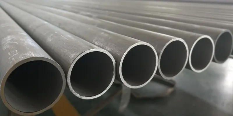
The distinction is not about method quality. A handheld ferrite scope and a laboratory point count can both be correct and still disagree, because they are measuring different volumes of material under different physical principles. The producer's guidance is explicit that magnetic readings need a product-specific offset and a consistent measured section, and that cross-reference measurements with a reference method should be performed where possible.
The matrix below is the single most useful tool when reviewing a supplier's inspection and test plan. For each row, ask whether the plan places the test at the location where the risk actually sits. A plan made entirely of surface rows can be perfectly executed and still fail to characterise a heavy section.
Table 13. Test method versus sampling depth: the heavy-section decision matrix
|
Method |
Surface |
T/4 |
Core / T/2 |
Detects intermetallic phase? |
Destructive? |
|
Visual and dimensional |
Yes |
No |
No |
No |
No |
|
Handheld XRF / PMI |
Yes |
No |
No |
No |
No |
|
Magnetic ferrite scope |
Yes |
Only on a machined step |
Only on a cut section |
No; it measures phase balance, not precipitates |
No |
|
Portable hardness |
Yes |
Only on a machined step |
Only on a cut section |
Not reliably |
Essentially no |
|
Liquid penetrant |
Yes |
No |
No |
No |
No |
|
Ultrasonic flaw detection |
Yes |
Yes |
Yes |
No |
No |
|
Radiography |
Yes |
Yes |
Yes |
No |
No |
|
Tensile specimen |
Only if wrongly taken |
Yes |
Possible by deep sampling |
Indirectly, through ductility |
Yes |
|
Charpy impact specimen |
Only if wrongly taken |
Yes |
Possible by deep sampling |
Yes, as an A923 Method B classification |
Yes |
|
Metallography, ASTM E562 / E1245 |
Only if the section is cut |
Yes |
Yes |
Yes, with suitable etch |
Yes |
|
ASTM A923 Methods A / B / C |
Not representative |
Yes |
Yes, at slowest-cooling region |
Yes, by design |
Yes |
|
ASTM G48 Method A |
Only if wrongly taken |
Yes |
Yes, at slowest-cooling region |
Yes, through corrosion performance |
Yes |
|
EBSD or X-ray diffraction |
Not representative |
Yes |
Yes |
Yes, as a reference technique |
Yes |
Notice that the two most widely available non-destructive volumetric methods, ultrasonic testing and radiography, appear in the middle of the table with a clear no in the intermetallic column. That is not a criticism of the methods. It is a reminder that finding a crack and finding a phase are different problems.
Can Ultrasonic Testing or Radiography Find Intermetallic Phases?
No. Ultrasonic testing and radiography detect discontinuities such as cracks, voids, inclusions and lack of fusion. Sigma and chi phase are finely dispersed precipitates at grain boundaries, not voids, so a heavy section can be ultrasonically clean and metallurgically damaged at the same time.
Ultrasonic examination works by sending a sound wave into the part and listening for reflections from interfaces with a different acoustic impedance. Radiography works by measuring differences in absorption through the thickness. A few volume percent of a fine intermetallic precipitate distributed along phase boundaries produces neither a strong discrete reflector nor a measurable density contrast at normal industrial sensitivity.
This is a particularly expensive misunderstanding because it feels complete. A buyer who orders full-volume UT, PMI on every piece, hardness checks and a 3.1 certificate has commissioned a serious-looking package, and every one of those tests can pass on a section whose core impact toughness has collapsed. The missing tests are the microstructural and mechanical ones.
Ultrasonic testing still has a real role in heavy duplex sections, just a different one: centreline segregation severe enough to open into discontinuities, forging bursts, laminar defects in heavy plate, and wall thickness verification. Use it alongside A923, not instead of A923.
Table 14. What each NDT method is looking for, and the question it leaves unanswered
|
Method |
Finds |
Does not find |
Question left unanswered |
|
Ultrasonic testing |
Internal planar and volumetric discontinuities, laminations, wall loss |
Phase balance, sigma, chi, 475 degrees Celsius embrittlement |
Is the microstructure correct? |
|
Radiography |
Voids, inclusions, shrinkage, lack of fusion in welds |
Fine intermetallic precipitates |
Is the corrosion resistance intact? |
|
Eddy current |
Near-surface and surface-breaking flaws, some sorting by conductivity |
Core condition, precipitates |
Is the core tough? |
|
Liquid penetrant |
Surface-breaking cracks and porosity |
Anything below an open surface |
Is the core tough? |
|
Magnetic particle |
Surface and near-surface flaws in magnetic material |
Austenite fraction and precipitates |
Is the phase balance in range? |
Practical note: If an inspection and test plan for a duplex heavy section contains no destructive test at a defined depth, it is a screening plan. Say so explicitly in the purchase documents, then add the through-thickness evidence as a separate priced line item.
Why Can a Pitting Corrosion Test Give a False Pass?
Because the result belongs to the coupon, and a coupon cut from the skin is not a coupon from the slowest-cooling region. ASTM G48 Method A is a powerful acceptance test for duplex stainless steel, but only when the specimen is taken from the location the standard and the project specification intend.
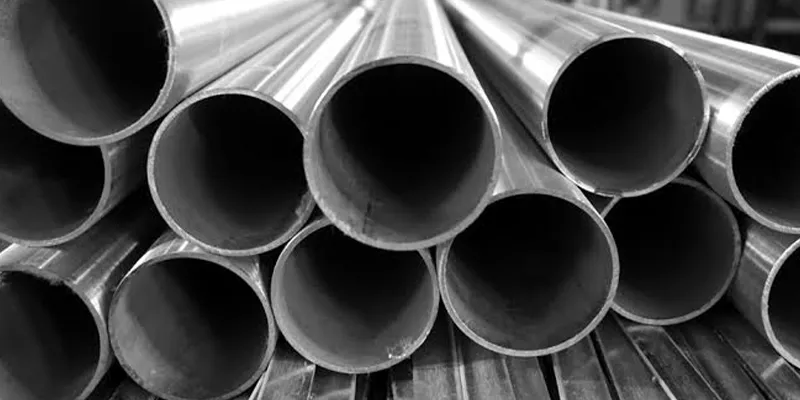
Sigma and chi phase are rich in chromium and molybdenum. When they form, they pull those elements out of the surrounding matrix, leaving depleted zones immediately around the precipitate. Pitting initiates in those depleted zones. The corrosion rate or the critical pitting temperature therefore acts as an amplifier: a small amount of precipitate that barely moves hardness can produce a clear failure in a ferric chloride test.
That sensitivity is exactly why test location matters. A G48 coupon machined from the rapidly quenched outer layer can be clean while a coupon from mid-thickness of the same plate pits heavily. The same applies to a Charpy specimen, a ferrite cross-section and an A923 etch. Every one of these tests is only as good as the sampling plan behind it.
Reported acceptance conditions for super duplex vary between project specifications, including test temperature, exposure duration and the maximum permitted weight loss or the absence of visible pitting at a specified magnification. Do not import a temperature from a different grade or a different data sheet. State the grade, the product form, the coupon location, the test method, the temperature, the duration and the acceptance criterion together.
Table 15. Coupon origin and the risk it creates in a pitting or A923 test
|
Coupon origin |
Likely result on a slowly cooled heavy section |
Risk introduced |
How to close the gap |
|
Outer skin, ground and polished |
Often passes |
False pass; the fastest-cooled material is the least likely to contain precipitate |
Take the acceptance coupon from the marked slowest-cooling region |
|
A small sacrificial coupon attached to a large forging |
Often passes |
Coupon quenches faster than the forging body |
Use a QTC representative in size and thermal cycle, heat treated with the load |
|
Quarter-thickness, T/4 |
Usually representative of bulk |
May still miss a narrow centreline band |
Add a T/2 cross-section examination where the specification calls for it |
|
Mid-thickness, T/2, slowest-cooling region |
The meaningful result |
Destructive and requires planned test material |
Design the test material into the forging or plate order from the start |
|
Region affected by repair welding or hot straightening |
Usually fails |
Correctly identifies local damage but may not represent the whole piece |
Map the affected area, then decide between re-anneal and rejection |
Practical note: A useful audit question: before any destructive test is performed, can the supplier show on a drawing where the coupon will be cut? If the answer is decided by the machine shop on the day, the certificate will describe the most convenient piece of metal, not the most important one.
What Does a Mill Test Certificate Actually Certify?
A mill test certificate reports the results of the tests that were performed, on the samples that were taken, at the locations that were chosen. It does not certify that the whole cross-section is free of detrimental intermetallic phase, and ASTM A923 says so explicitly.
EN 10204 Type 3.1 is a manufacturer's declaration that the supplied products comply with the order requirements, with test results based on non-specific or specific inspection carried out by the manufacturer's own authorised representative. Type 3.2 adds an independent third-party witness or verification. Both are documents about a defined inspection scope. Neither expands that scope by itself.
This is where the phrase compliant on paper comes from. Chemistry within the UNS range, tensile results above the minimum, hardness below the ceiling, and a 3.1 or even 3.2 certificate can all be true while a small amount of sigma phase sits at mid-thickness. ASTM A923's scope language addresses exactly this: compliance with the applicable product specification's chemical and mechanical requirements does not necessarily indicate that detrimental intermetallic phases are absent.
The remedy is not to distrust certificates. It is to write the additional evidence into the order as named tests with named locations, so that the certificate has something to report. A 3.2 certificate that witnesses the same surface-only test plan is a better-signed version of the same blind spot.
Table 16. What each certificate layer covers, and what still needs to be ordered separately
|
Layer |
What it establishes |
What it does not establish |
Typical addition for a heavy duplex section |
|
EN 10204 Type 3.1 |
Manufacturer's own test results against the order requirements |
Independent witnessing; any test not in the order |
Named A923, G48, ferrite point count and impact tests at a defined depth |
|
EN 10204 Type 3.2 |
Independent witnessing of the agreed inspection scope |
Anything outside that agreed scope |
Extend the witnessed scope to coupon location and heat-treatment records |
|
NORSOK M-650 qualification, where invoked |
The manufacturer is qualified to produce the special-grade material |
That this individual piece is free of precipitate |
M-630 material data sheet requirements plus lot-specific testing |
|
Heat-treatment chart record |
Time, temperature and quench history of the load |
The resulting microstructure at T/2 |
Cross-section metallography at the slowest-cooling region |
|
PMI report on every piece |
Grade identity at the measured surface point |
Carbon, nitrogen, centre chemistry or phase balance |
Laboratory chemistry on a defined sampling frequency |
In short, a certificate is a contract about evidence. If the contract names only surface evidence, the buyer has purchased surface evidence, however impressive the letterhead.
How Should a Buyer Specify a Duplex Heavy Section?
Specify the worst location, not just the alloy. A workable purchase order names the grade and UNS number, the governing product specification, the governing section thickness, the coupon locations, the through-thickness tests, the acceptance criteria and the heat-treatment records, all in one place.
Most disputes about duplex heavy sections are not metallurgy disputes. They are specification gaps discovered after the part has been machined. The supplier delivered what the order said; the buyer assumed the order said more. A short, precise inspection clause closes nearly all of those gaps at almost no cost.
The eight-step procedure in the appendix is written in the order a buyer would actually execute it. It is deliberately independent of any particular grade or standard edition, so it can be attached to an enquiry for plate, bar, forging, casting or heavy-wall pipe.
Table 17. Specification checklist: the ten clauses that prevent a surface-only acceptance
|
Clause |
What to write |
Why it is there |
|
1. Material identity |
Grade, UNS number, product form, ASME or ASTM product specification and edition |
Stops grade substitution and ambiguous dual naming |
|
2. Governing section |
The maximum section thickness that controls heat treatment |
Makes the thermal gradient an explicit variable |
|
3. Heat treatment |
Solution-annealing band, soak rule for the governing section, maximum transfer time, quench medium and agitation |
Controls the process that creates the gradient |
|
4. Coupon location |
A marked drawing showing T/4 and the identified slowest-cooling region |
Removes the phrase representative sample |
|
5. Chemistry |
Ladle analysis plus a product or centre sample where segregation is a concern; laboratory method for carbon and nitrogen |
Closes the XRF blind spot |
|
6. Phase balance |
Acceptance range, reference method such as ASTM E562, number of fields, and the magnetic instrument correlation offset |
Avoids the up-to-20-percent surface bias |
|
7. Intermetallic phase |
ASTM A923 Methods A, B or C as applicable, sampled at the slowest-cooling region |
The only routine screening for the actual failure mode |
|
8. Toughness and corrosion |
Charpy temperature and energy, plus ASTM G48 Method A conditions if required |
Confirms the properties that surface readings cannot see |
|
9. Volumetric NDT |
UT or RT scope appropriate to the product form |
Finds discontinuities, explicitly not phases |
|
10. Evidence |
Certificate type, witnessed tests, heat-treatment charts and test-location records |
Makes the whole package auditable |
Practical note: Ask for the inspection and test plan before the order is placed, not with the final documents. Once a heavy forging has been quenched and machined, a mid-thickness coupon is either impossible to obtain or expensive to justify.
What Are the Most Common False-Pass and False-Fail Scenarios?
Nearly all false passes come from a sampling-location error, and nearly all false fails come from a surface-preparation or calibration error. Separating those two families saves a great deal of avoidable re-testing.
A false pass is dangerous because nothing in the paperwork looks wrong. A false fail is expensive because it triggers a hold, a re-test, and sometimes a scrap decision on a perfectly good heavy forging. Both are common enough that a good inspection plan anticipates them with a defined confirmation route.
The confirmation rule is simple: treat an out-of-range reading as a result, not as a bad reading. Re-measure on a properly prepared surface at a second location, check the calibration blocks, and escalate through the defined procedure instead of taking repeated shots until a preferred number appears. Conversely, treat an in-range surface reading as a screening result, not as a release criterion, whenever the governing section is heavy.
Table 18. Typical surface-reading errors on duplex heavy sections
|
Scenario |
What the surface shows |
What the section actually is |
Consequence |
Control |
|
Slow core quench on thick plate |
PMI and hardness normal; ferrite scope in range at the skin |
Intermetallic phase and low toughness at T/2 |
False pass; in-service pitting or brittle fracture |
A923 or G48 coupon from the slowest-cooling region |
|
Small QTC on a large forging |
Tensile and impact pass |
QTC cooled faster than the forging body |
False pass |
Size-representative QTC, heat treated with the load |
|
Centreline segregation |
Grade chemistry confirmed on the surface |
Local chemistry and PREN differ at the core |
False pass on corrosion margin |
Centre sample plus cross-section metallography |
|
Magnetic reading on a ground or cold-worked surface |
Ferrite reads low |
Phase balance is actually in range |
False fail |
Defined surface preparation, grade-specific calibration, E562 cross-reference |
|
Oxide, scale or coating left on the test spot |
Chemistry drifts outside the grade window |
Material is correct |
False fail |
Grind to bright metal; record surface preparation |
|
Reading close to a curved edge or a thin section |
Ferrite value drifts |
No real change in phase balance |
False fail |
Consistent geometry, correct probe, product-specific offset |
|
Nitrogen below specification |
PMI still identifies the grade correctly |
Phase balance and pitting resistance are compromised |
False pass |
Laboratory OES or combustion analysis on a defined frequency |
|
Local repair weld after final anneal |
Surrounding metal measures normally |
Affected zone contains precipitate |
False pass |
Test the affected region or re-anneal the whole piece |
What Does Through-Thickness Verification Cost Compared With a Rejected Batch?
The added inspection is a small, predictable line item; the rejected heavy section is a large, unplanned one. The comparison is not really about test price, it is about when the information arrives: before machining or after installation.
A through-thickness package adds a small number of destructive tests, a cross-section sample, and some metallographic and impact work. Those are planned costs with a known lead time, and on a heavy section they are a small fraction of the material and machining value of the piece. A missed intermetallic problem is discovered either during final machining, during a project witness test, or in service, and each of those discovery points is more expensive than the last.
Be careful with invented precision here. Test prices vary by region, laboratory accreditation, specimen count and turnaround, and a blog article that quotes a universal dollar figure would be less credible, not more. The defensible comparison is structural: count the tests, count the pieces at risk, and compare the verification window with the replacement lead time for a heavy forging or a thick plate.
Table 19. Three verification tiers, compared by evidence and by when a defect would be found
|
Tier |
What it contains |
Relative effort |
When a core defect is discovered |
Appropriate for |
|
Tier 1: screening |
PMI on every piece, surface hardness, visual and dimensional, certificate review |
Low |
Usually not before service |
Thin sections, non-critical duty, known qualified supplier |
|
Tier 2: representative |
Tier 1 plus tensile and Charpy at a defined depth, ferrite by point counting on a cross-section, laboratory chemistry including nitrogen |
Moderate |
Before shipment, for the sampled lot |
Medium plate, standard duplex pressure parts |
|
Tier 3: through-thickness |
Tier 2 plus A923 at the slowest-cooling region, G48 where specified, marked coupon drawing, witnessed heat-treatment records, UT or RT for discontinuities |
Higher, but still a fraction of a single heavy component |
Before machining is complete |
Heavy plate, large forgings, castings, sour or seawater critical service |
The decisive number is not the cost of the extra tests. It is the replacement lead time for a 100 mm plate or a large custom forging, plus the machining already sunk into it, plus the project schedule. Against that, a marked coupon drawing and three extra tests are inexpensive insurance.
When Is a Heavy Duplex Section the Wrong Choice Altogether?
When the section is thicker than the supplier can quench correctly, when the service temperature sits in an embrittlement range, or when the corrosion duty can be met more reliably with a different design. In those cases the right answer is not better inspection, it is a different specification.
Every mitigation in this article assumes the supplier can deliver a fast, uninterrupted quench through the governing section. If the furnace-to-tank transfer, the tank size, the agitation or the section geometry cannot achieve that, no amount of testing will make the centre correct; testing will only document the failure more thoroughly. Producer guidance notes that for super duplex grades the practical limit on certifiable section size is set by exactly this constraint.
Temperature is the other hard boundary. Duplex grades are not intended for prolonged service in the 300 to 525 degrees Celsius range where 475 degrees Celsius embrittlement develops, nor in the 600 to 1000 degrees Celsius range where sigma and chi form. A heavy component in a hot cyclic duty is being asked to fail slowly from the inside.
Finally, consider whether the section needs to be solid duplex at all. Clad construction, a thinner pressure boundary with external reinforcement, a 6 percent molybdenum super-austenitic grade, or a nickel alloy can each deliver the required corrosion performance without asking a thick duplex cross-section to survive a quench it was never going to survive.
Table 20. Situations where a different route is more reliable than inspecting a heavy duplex section harder
|
Situation |
Why the heavy section is the wrong answer |
More robust route |
|
Governing section exceeds the supplier's demonstrated quench capability |
The centre cannot be pulled through the precipitation window fast enough |
Redesign into thinner sections, or qualify a supplier with an appropriate quench facility |
|
Continuous service in the 300 to 525 degrees Celsius band |
475 degrees Celsius embrittlement develops over time |
Austenitic or nickel-based alloy selected for the temperature |
|
Repeated thermal cycles in the sigma range |
Intermetallic phase reforms after each exposure |
Change the process or the material family |
|
Cryogenic duty with high fracture-criticality |
The ferritic phase loses toughness at very low temperature |
Austenitic stainless or nickel alloy with a qualified low-temperature toughness |
|
Corrosion duty needs PREN above 40 but the geometry is massive |
2507 is the least forgiving grade for a thick section |
Clad construction, 6Mo super-austenitic, or a nickel alloy |
|
Very large casting with unavoidable hot spots |
Last-to-freeze regions are inherently slow cooling |
Fabricated assembly from wrought plate and forgings, each with a controllable section |
|
Project cannot allow destructive testing at the worst location |
No defensible evidence for the core is possible |
Reduce section size, change product form, or accept a lower duty with a documented basis |
Practical note: The most professional outcome of a heavy-section review is sometimes a decision not to buy a heavy duplex section. Saying so early is a stronger signal of engineering competence than delivering a perfectly documented marginal component.
How to Verify a Duplex Heavy Section in Eight Steps?
Verification is a sequence of decisions about location, not a single test. Fix the governing section and the coupon positions before the order is placed.
- Define the governing section. Identify the maximum thickness that will control heating and quenching, and record it on the drawing. Do not let a thinner, easier-to-machine region stand in for it.
- Identify the slowest-cooling region. Mark the location that will spend the longest time in the intermetallic precipitation window. ASTM A923 names this as the region to test for ordinary heat treatment.
- Fix the specimen locations before the order. Show T/4, T/2, the coupon orientation and the test material on a marked drawing, and reference that drawing in the purchase order.
- Specify the heat-treatment evidence. State the solution-annealing band, the soak rule for the governing section, the maximum furnace-to-quench transfer time and the quench medium and agitation. Ask for the chart record.
- Separate identity testing from property testing. Use handheld PMI for fast grade screening, and laboratory analysis for carbon and nitrogen. Neither replaces a microstructural or mechanical test.
- Correlate the fast ferrite method. Set an acceptance range, a reference method such as ASTM E562 point counting, the number of fields and the correlation offset for the magnetic instrument on that product route and thickness.
- Order the through-thickness tests. Add ASTM A923 structure classification, Charpy impact at the specified temperature and depth, and ASTM G48 where the duty requires it, all sampled from the marked slowest-cooling region.
- Make the evidence auditable. Require the certificate type, witnessed tests, calibration records, coupon-location records and heat-treatment charts as a single traceable package tied to the heat and piece number.
Frequently Asked Questions
Q01. What is a duplex stainless steel heavy section?
Answer: A duplex stainless steel heavy section is a product thick enough for the centre and the surface to experience meaningfully different heating and cooling rates. In purchasing practice this becomes a concern above roughly 25 to 50 mm and a governing concern for large forgings, thick tube sheets, heavy-wall fittings and castings.
Q02. Why can a surface reading be misleading on a thick duplex plate?
Answer: Because the surface quenches fastest and the centre quenches slowest, so the two regions can develop different microstructures in the same heat-treatment cycle. A surface reading describes the fastest-cooled material, which is the least likely to contain intermetallic phase.
Q03. What does ASTM A923 say about sampling location?
Answer: ASTM A923 says the tests must be applied to the region most likely to promote intermetallic formation, and that in ordinary heat treatment this is the slowest-cooling region. It notes that sampling from that location may be necessary to characterise the piece, except for rapidly cooled material.
Q04. Does passing chemistry and tensile testing prove a duplex part is free of sigma phase?
Answer: No. ASTM A923 explicitly states that compliance with the applicable product specification's chemical and mechanical requirements does not necessarily indicate that detrimental intermetallic phases are absent. That is the reason the standard exists.
Q05. Can a ferrite scope reading be lower than the real ferrite content?
Answer: Yes. Producer guidance from Outokumpu reports that a surface reading on a rolled product in final condition can be up to 20 percent lower than the actual ferrite content, and that results vary significantly depending on which cross-section is measured.
Q06. What is the reference method for measuring ferrite content?
Answer: Metallographic point counting to ASTM E562 or image analysis to ASTM E1245 on a polished and etched cross-section is the reference approach, with fields distributed across the section. X-ray diffraction and EBSD are used as reference techniques, while magnetic instruments are fast production methods that need a product-specific calibration offset.
Q07. Why can handheld XRF PMI not fully verify a duplex grade?
Answer: Handheld XRF cannot determine carbon, nitrogen, boron or oxygen, and in steel its signal comes from only the top few to a few tens of micrometres. Nitrogen is a specified, austenite-forming addition in duplex steel, so PMI cannot verify one of the elements that controls the phase balance.
Q08. Can PMI detect a wrong heat treatment?
Answer: No. PMI verifies elemental chemistry at the measured point. It says nothing about microstructure, heat-treatment condition, strength, toughness or phase balance, which require metallography, mechanical testing or corrosion testing.
Q09. Does a hardness test detect sigma phase?
Answer: Not reliably. Small intermetallic fractions can cause a large drop in impact toughness and pitting resistance while hardness changes very little, and a surface indentation does not reach the core where the phase concentrates. Hardness is a compliance ceiling, not a microstructural test.
Q10. Can ultrasonic testing find intermetallic precipitates?
Answer: No. Ultrasonic testing and radiography detect discontinuities such as cracks, voids, laminations and inclusions. Fine intermetallic precipitates at grain boundaries do not produce a discrete reflector or a usable density contrast at normal industrial sensitivity.
Q11. Where should tensile and impact specimens be taken on a heavy duplex forging?
Answer: From a defined depth below the surface, commonly quarter-thickness or midway between the centre and the surface, on test material that shares the forging's size, chemistry, forging ratio and heat-treatment cycle. A small coupon that quenches faster than the forging body can produce a false pass.
Q12. Why is the centre of a thick plate more at risk than the surface?
Answer: The centre is last to reach the solution-annealing temperature, slowest to cool through the 600 to 1000 degrees Celsius precipitation window, and may retain centreline segregation from solidification. All three effects push it toward intermetallic formation and lower local corrosion resistance.
Q13. Which grade is more sensitive to a slow core quench, 2205 or 2507?
Answer: 2507 is more sensitive. Its higher chromium, molybdenum and nitrogen content gives higher strength and PREN but shifts the precipitation curve to shorter times, so the same section size that is comfortable for 2205 can be marginal for 2507.
Q14. What temperature range is most dangerous for duplex stainless steel?
Answer: ASTM A923 identifies approximately 320 to 955 degrees Celsius as the range in which intermetallic compounds can form, while sigma and chi precipitation is commonly concentrated around 600 to 1000 degrees Celsius with the fastest kinetics near 700 to 900 degrees Celsius. Long exposure around 300 to 525 degrees Celsius causes 475 degrees Celsius embrittlement.
Q15. Why is a stress-relief heat treatment a problem for duplex steel?
Answer: Because the usual stress-relief temperature range sits inside the intermetallic precipitation window. A cycle intended to relieve stress can instead precipitate sigma or chi phase, so any thermal operation after the final anneal normally requires a full re-solution-anneal and re-quench.
Q16. Why is the furnace-to-quench transfer time important?
Answer: Time in still air between the furnace and the water is uncontrolled slow cooling through the precipitation window. Producer guidance for duplex grades is to keep that delay as short as practical so that harmful phase cannot begin to form before the quench.
Q17. Can a pitting corrosion test give a false pass?
Answer: Yes, if the coupon is cut from the skin. ASTM G48 Method A is a sensitive indicator of intermetallic damage, but only for the volume of metal actually tested, so the coupon must come from the marked slowest-cooling region.
Q18. What does an EN 10204 Type 3.1 or 3.2 certificate actually prove?
Answer: It proves that the agreed inspection scope was carried out and witnessed to the stated degree. It does not expand that scope: if the order names only surface tests, a 3.2 certificate witnesses the same surface-only blind spot.
Q19. What is the minimum extra evidence to order for a duplex heavy section?
Answer: A marked coupon-location drawing, ferrite by point counting on a cross-section, ASTM A923 testing at the slowest-cooling region, Charpy impact at a defined depth and temperature, and the heat-treatment chart record. Add ASTM G48 where the corrosion duty requires it.
Q20. Can a thin duplex part develop a heavy-section problem?
Answer: Yes. A repair weld, flame-cut edge, hot straightening pass or local stress-relief cycle creates a region with its own thermal history. Surface readings on neighbouring unaffected metal will be normal while the affected zone contains precipitate.
Q21. Should a buyer trust a ferrite scope reading at all?
Answer: Yes, as a fast screening and process-control tool with a defined calibration, surface preparation, measurement location and product-route offset. It should not be the sole release criterion for a heavy section, and it should be cross-referenced against a reference method.
Q22. When should a heavy duplex section be avoided altogether?
Answer: When the section exceeds the supplier's demonstrated quench capability, when service falls inside an embrittlement temperature range, or when the corrosion duty can be met by cladding, a thinner design, a 6Mo super-austenitic grade or a nickel alloy. Better inspection cannot fix a quench the geometry cannot support.