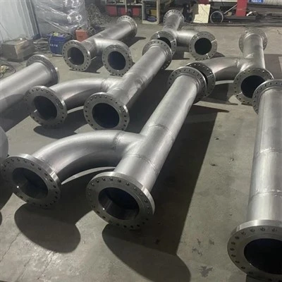
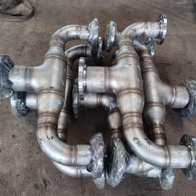
Track cumulative thermal exposure by linking every original weld pass, repair pass, and relevant reheating event to the same physical pipe location. Record welding parameters, interpass temperatures, repair geometry, and-when engineering assessment requires it-measured or validated temperature–time histories. A repair count or a total of heat-input values cannot, by itself, prove that duplex stainless steel remains fit for service.
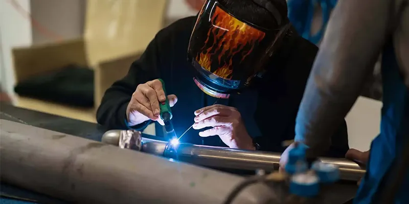
For manufacturers and fabricators working with duplex pipe, the objective is straightforward: preserve corrosion resistance and toughness while removing defects. This requires a location-based thermal history, not simply a signed repair report.
Why does cumulative thermal exposure matter in duplex pipe weld repairs?
Repeated heating can change the balance between ferrite and austenite and promote harmful phases, so the condition of a repaired region depends on its full thermal history-not just its final weld pass.
Duplex stainless steel combines ferrite and austenite, two different crystal structures that contribute to its performance. Welding heats the weld and nearby heat-affected zone, or HAZ. The peak temperature and subsequent cooling influence how these structures develop. Insufficient heat input can leave excessively high ferrite; excessive heat input and slow cooling increase the risk of intermetallic phases that reduce toughness and corrosion resistance.
A repair adds another cycle to metal that may already have experienced original welding, adjacent passes, and previous repairs. Research identifies repeated heating within approximately 400–1030°C as capable of causing unwanted transformations, with particular concern around 700–1000°C. These are explanatory ranges, not universal shop-floor acceptance limits: composition and thermal history determine reaction rates.
Grinding out defective weld metal does not automatically remove the previously heated material beside or beneath it. A useful repair record therefore follows the retained HAZ as well as the replacement weld metal.
How does thermal control differ between standard duplex and superduplex pipe?
Both require qualified limits on heat input and interpass temperature, but superduplex generally uses a lower interpass temperature ceiling. IMOA gives general maxima of 150°C for lean and standard duplex and 100°C for superduplex. The approved welding procedure governs the actual job.

|
Control point |
Lean and standard duplex |
Super duplex |
|
General interpass guidance |
Maximum 150°C |
Maximum 100°C |
|
Heat-input range |
Use the qualified grade-, process-, and geometry-specific range |
Use the qualified grade-, process-, and geometry-specific range |
|
Repair-history requirement |
Track original and repair cycles at the retained material |
Apply the same traceability; the lower interpass ceiling needs explicit attention |
|
Acceptance basis |
Governing specification, qualified procedure, and required tests |
Governing specification, qualified procedure, and required tests |
The temperature guidance comes from IMOA; the tracking and acceptance entries describe the recommended record structure rather than a separate code requirement.
Interpass temperature is the workpiece temperature before a subsequent pass. It is not the peak HAZ temperature and is not the temperature at which sigma phase necessarily forms. Its importance is that a warmer starting condition affects cooling during the next weld cycle.
Do not transfer a heat-input window from a different duplex grade, wall thickness, welding process, or repair configuration without checking qualification coverage. TWI emphasizes staying within qualified procedure limits and controlling weld preparation dimensions because geometry changes can change welding behavior.
Which tracking method best captures cumulative thermal exposure?
A location-based pass log is the practical foundation; instrumented temperature histories and validated thermal models add detail where the repair risk justifies them. No single measurement replaces the others.
|
Method |
What it captures |
Main limitation |
Recommended role |
|
Repair count |
Number of recorded repair episodes |
Omits pass count, location, cooling, and overlap |
Administrative trigger for review |
|
Per-pass arc-energy log |
Electrical energy per unit weld length |
Does not measure the local temperature–time cycle |
Routine welding control |
|
Interpass-temperature log |
Starting thermal condition before each pass |
Does not capture the hottest HAZ or all cooling behavior |
Routine verification against the WPS |
|
Thermocouple recording |
Temperature against time at sensor locations |
Cannot directly describe uninstrumented material |
Repair trials and selected critical work |
|
Validated thermal model |
Estimated temperature histories across the repair |
Depends on geometry, heat-source assumptions, and validation |
Engineering assessment of difficult-to-measure regions |
This comparison is a proposed engineering workflow. Its basis is the documented importance of heat input, interpass temperature, cooling, and material thermal history; IMOA specifically prefers electronic probes and thermocouples for interpass monitoring.
The strongest records connect these methods. For example, an instrumented qualification trial can establish representative cooling behavior, while production records show whether actual welding stayed within the approved process envelope. A model should not be treated as proof merely because it produces a detailed temperature plot.
What information should a duplex pipe repair log contain?
The log should connect material identity, exact repair location, every relevant heating event, and final inspection evidence. The following is a recommended template, not a universal code-mandated form.
1. Material and joint identity: pipe or spool number, heat number, grade, outside diameter, wall thickness, weld ID, and material certificate reference.
2. Repair geometry: clock position, axial position, excavation length, width and depth, remaining wall, and overlap with earlier repairs.
3. Procedure identity: welding procedure specification (WPS), supporting procedure qualification record (PQR), revision, process, filler classification, and welder identification.
4. Pass data: original or repair event ID, pass number, start and finish times, current, voltage, travel speed, and calculated arc energy or defined heat input.
5. Temperature data: interpass reading, measurement time and location, instrument identity, and calibration status. Where recorded, retain complete temperature–time files and sensor-location sketches.
6. Supporting controls: shielding and backing-gas details, cleaning, cooling method, and relevant deviations or interruptions.
7. Release evidence: inspection results, any required metallurgical or corrosion testing, deviation disposition, and authorized approval.
Use one continuing joint record rather than starting an unrelated document after each excavation. A circumferential sketch should show which retained regions were reheated by neighboring repairs. TWI's guidance supports close control of preparation, parameters, cleanliness, and shielding; ASTM A923 emphasizes examining regions most likely to contain detrimental phases.
How should heat input be calculated without confusing it with thermal exposure?
Calculate energy per unit length for process control, but do not interpret the sum across passes as a metallurgical damage limit.
For a steady arc, gross arc energy can be expressed as:
E = 60 × V × I / (1000 × v)
Here, E is arc energy in kJ/mm, V is arc voltage, I is current in amperes, and v is travel speed in mm/min. If the governing procedure defines net heat input using thermal efficiency, use Q = ηE, where η is the specified efficiency factor. State the convention; do not compare gross and efficiency-adjusted values as though they were identical.
For pulsed or waveform-controlled welding, use the energy determination method required by the governing standard and approved procedure. Multiplying average current by average voltage may not represent the true average power.
Consider two repairs made with the same arc energy per pass. One starts on a cooler pipe and allows longer cooling intervals; the other starts near its interpass ceiling and reheats an overlapping location sooner. Equal arc energy does not establish equal local temperature history. This distinction follows from the importance of workpiece temperature and cooling highlighted by IMOA.
Can time in a temperature band quantify cumulative exposure?
Time in a defined temperature band can compare measured thermal histories, but it is a screening metric-not a universal acceptance criterion.
For a fixed material location x, an engineering review can define:
C(x; T1, T2) = sum of the time spent between T1 and T2 over the recorded thermal cycles.
Select T1 and T2 for the specific transformation being investigated, grade, and assessment method. Report peak temperatures and individual cycles alongside the total. An example review might examine exposure within 700–1000°C because research identifies that interval as particularly important for unwanted transformations; it must not invent a universal allowable number of seconds.
Two histories with the same band-time total may produce different microstructures because reaction rates vary strongly with temperature and composition. ASTM A923 explicitly states that precipitation speed depends on composition and the thermal or thermomechanical history of the individual piece.
Attach thermocouples at documented locations selected by the responsible engineer, and select sampling and sensor response adequate for the expected transients. A surface sensor does not automatically measure the root or hottest subsurface HAZ. If the repair changes geometry, reassess whether an earlier sensor layout or thermal model still represents the retained material.
Does a second or third repair automatically require pipe replacement?
No universal safe repair count can be established from repair number alone. Further welding requires review against the governing construction or repair rules, project specification, procedure coverage, and actual retained-material history.
The following comparison is illustrative, not test data:
|
Repair history |
What the count conceals |
Recommended engineering question |
|
One repair with many overlapping passes |
A single repair episode may contain repeated local reheating |
Does the qualified repair sequence represent this exposure? |
|
Two repairs at separated locations |
The retained HAZs may not overlap directly |
Are location, geometry, and heat flow sufficiently documented? |
|
Two repairs in the same excavation |
Previously heated material may remain beside the new weld |
Is additional qualification, testing, or replacement needed? |
|
Unknown original pass history |
The exposure baseline cannot be reconstructed reliably |
Can the uncertainty be resolved, or should the affected section be replaced? |
Stop and obtain engineering disposition when a procedure limit is exceeded, repair overlap is uncertain, or the approved repair arrangement no longer represents the work. A later compliant pass does not erase an earlier excursion. The technical basis for reviewing full history is the dependence of precipitation and microstructure on thermal history.
Which inspections can confirm an acceptable repaired weld?
Use the required defect inspections together with the specified metallurgical and performance evidence. A clean radiograph or acceptable ferrite reading alone does not establish that harmful intermetallic phases are absent.

Radiography, ultrasonic testing, and surface examinations address particular discontinuities within their qualified capabilities. Ferrite measurement provides phase-balance information at the measured locations, but it is not equivalent to direct assessment of detrimental phases or corrosion performance.
ASTM A923 provides three methods for certain listed duplex grades: Method A, sodium hydroxide etch examination; Method B, Charpy impact testing; and Method C, ferric chloride corrosion testing. Its scope stresses appropriate sampling location and orientation. Other grades may require ASTM A1084 or another specified approach; do not assume these standards are interchangeable or that every repair requires every test.
Where destructive testing is specified, use approved qualification or representative repair specimens as required by the project. Set test selection, sampling, and acceptance criteria before production-not after an unfavorable result. Even compliance with a product specification's chemical and mechanical requirements does not necessarily prove the absence of detrimental phases.
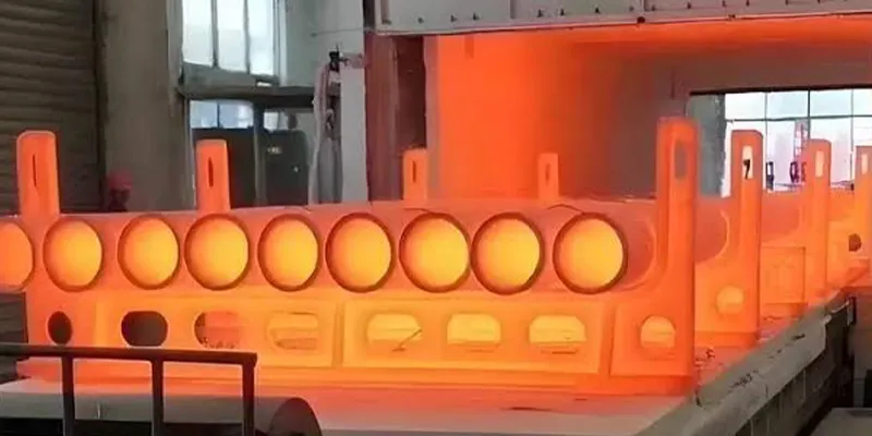
Can post-weld heat treatment reset a duplex repair history?
Conventional stress-relief heating is not a general reset method for duplex stainless steel and can make its properties worse.
IMOA warns that post-weld heating can precipitate harmful phases. Full solution annealing followed by water quenching is fundamentally different from local stress relief, and TWI notes that whole-component solution treatment is often impractical for welded structures. Any proposed treatment needs grade-specific engineering and procedural approval.
Do not use a generic heat-treatment cycle to justify additional repairs or erase the record of earlier heating. Keep any approved treatment within the component's permanent manufacturing history.
How can JN Alloy support a traceable duplex pipe repair program?
JN Alloy's published capabilities align with material supply, pipe-spool processing, and inspection support; project-specific repair qualification and acceptance must still be established separately.
JN Alloy identifies stainless steel, duplex steel, superduplex steel, and nickel alloys within its product range. Its website describes pipeline-product welding and pipe-spool processing, along with equipment for radiography, metallography, mechanical testing, positive material identification, and hydrostatic testing. These published capabilities provide a basis for discussing documentation and inspection requirements; they do not establish approval for every repair configuration or test method.
When specifying duplex pipe or prefabricated spools, request agreement on material traceability, WPS/PQR coverage, repair mapping, pass-by-pass records, and inspection hold points. The practical deliverable is an auditable record showing where heat was applied, how welding was controlled, and why the repaired joint was accepted.
Technical scope: This article provides general engineering guidance, not a production WPS, repair authorization, or code interpretation. Apply the project's governing documents and obtain approval from the responsible welding/materials engineer.