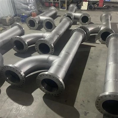
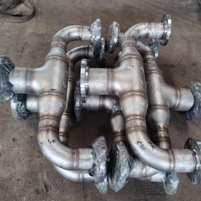
| Grade identity | 347 is UNS S34700 (EN 1.4550, X6CrNiNb18-10), an 18-8 austenitic stainless stabilized with niobium (columbium) so it resists intergranular corrosion after welding. See the 347 stainless steel product page. |
|---|---|
| Why it cracks | 347 welds are more prone to hot cracking than unstabilized 304L or 316L and even than 321, because niobium forms low-melting Nb(C,N) eutectics and suppresses the delta ferrite that normally absorbs them. |
| Ferrite window | Keep weld-metal ferrite in the FN 3-8 band (some codes allow FN 4-10). Below FN 3, solidification cracking risk climbs sharply; above FN 8-10, sigma-phase embrittlement in hot service becomes the new risk. |
| Three mechanism families | Most 347 weld cracks are solidification (hot) cracking, ductility-dip cracking, or reheat (stress-relief) cracking - each tied to a different temperature window and location. |
| Niobium is double-edged | Niobium gives 347 its high-temperature creep strength and stabilizes the weld against sensitization, but it is also the prime driver of both hot cracking and reheat cracking. |
| PWHT caution | 347 is usually stabilized enough to skip stress relief, but thick, highly restrained joints can develop reheat cracking during any 600-850 C heat treatment - so PWHT is a decision, not a default. |
| Investigate systematically | Treat a crack as a forensic problem: classify by location and morphology, confirm with NDE and microscopy, measure ferrite and chemistry, then match the mechanism to the temperature window before you repair. |
347 stainless steel welds crack more readily than ordinary 304L/316L because niobium - the element that makes 347 corrosion-resistant - also forms low-melting eutectics and suppresses the protective delta ferrite. The three mechanisms you will actually meet are solidification (hot) cracking, ductility-dip cracking, and reheat (stress-relief) cracking, each tied to a different temperature window.
The fix is never just 'weld it again': you need a systematic investigation - classify the crack, confirm with NDE and microscopy, measure ferrite and chemistry, and match the mechanism to the thermal history - then a ferrite-controlled repair. This article walks through every mechanism, the all-important ferrite-number window, how 347 compares with 321, filler and procedure choices, the post-weld-heat-treatment trap, and a practical step-by-step framework you can apply on the shop floor.
What Makes 347 Different From 304L and 316L, and Why Does That Matter for Welding?
347 is an 18-8 austenitic stainless steel whose carbon is locked up by niobium (columbium) instead of being removed by a low-carbon chemistry, and that single design choice is the root of both its strength and its weld-cracking habit. Unstabilized 304L and 316L rely on very low carbon (0.03 percent max) to avoid sensitization; 347 keeps normal carbon but binds it as stable niobium carbide, so the weld resists intergranular corrosion even after welding.
The cost of that advantage is metallurgical. Niobium is a strong austenite stabilizer, so it lowers the ferrite potential of the weld; and at stabilizing levels it forms Nb(C,N) eutectics that are low-melting and spread along grain boundaries. In 304L/316L the small amount of retained delta ferrite absorbs harmful segregates and breaks up the final liquid film, which is why those grades weld so well. In 347 the niobium works against you. The type-of-material overview and the composition and applications pages give the full grade picture; the rest of this article is about what that means at the weld.
Which Cracking Mechanisms Actually Occur in 347 Welds?
Almost every 347 weld crack falls into one of three families - solidification (hot) cracking, ductility-dip cracking, or reheat (stress-relief) cracking - with a fourth, less common, fusion-line mode called liquation cracking. Knowing which family you are dealing with is the first step of the investigation, because each has a different location, temperature window and cure.
The three 347 weld-cracking families at a glance
| Mechanism | Temperature window | Typical location | What drives it in 347 |
|---|---|---|---|
| Solidification (hot) cracking | During freezing (~final liquid) | Weld centerline, solidification sub-boundaries | Nb(C,N) low-melting eutectic + P/S/Si segregation; low ferrite |
| Ductility-dip cracking (DDC) | About 600-900 C on reheating | Weld metal / HAZ grain boundaries | Nb(C,N) precipitation; lost grain-boundary ductility |
| Reheat (stress-relief) cracking | 600-850 C hold (PWHT) | HAZ / weld-metal grain boundaries | NbC/NbN re-precipitation + residual stress |
| Liquation cracking | Peak thermal cycle at fusion line | HAZ just inside the fusion line | Grain-boundary NbC, phosphide/sulphide or sigma-austenite films melt |
What Is Solidification (Hot) Cracking and Why Is 347 Worse Than 321?
Solidification cracking is tearing that forms as the weld freezes, when a residual liquid film still lines the grain boundaries; in 347 it is among the most likely failure modes, and 347 is more crack-sensitive than titanium-stabilized 321 because niobium forms more harmful, more spreading low-melting constituents.
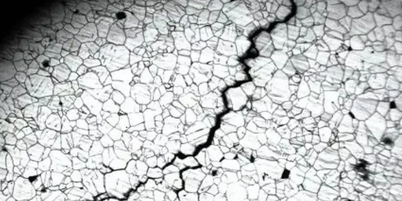
The crack appears as a branched, intergranular tear at the weld centerline or along solidification sub-boundaries, often invisible to the eye until dye penetrant is applied. Its severity tracks the solidification mode: a primary-ferritic (FA) freeze disrupts the liquid film and absorbs P, S and Si, while a primary-austenitic (A or AF) freeze leaves a continuous film that tears. Studies put the threshold for eliminating fissuring in fully-austenitic 347 weld metal at roughly FN 6 or higher, and other work found good weldability of 321/347 only with ferrite of 6 FN or greater.
Columbium-stabilized stainless is, across the literature, more prone to hot cracking than titanium-stabilized stainless - which is exactly why ER347 filler is the default and why ferrite must be designed in, not assumed.
What Is Ductility-Dip Cracking and Where Does It Appear in 347?
Ductility-dip cracking is a grain-boundary crack that opens when weld metal or heat-affected zone is reheated into roughly the 600-900 C range during multipass welding or post-weld heat treatment, and in 347 it is tied to niobium carbonitride precipitation that robs the boundaries of ductility.
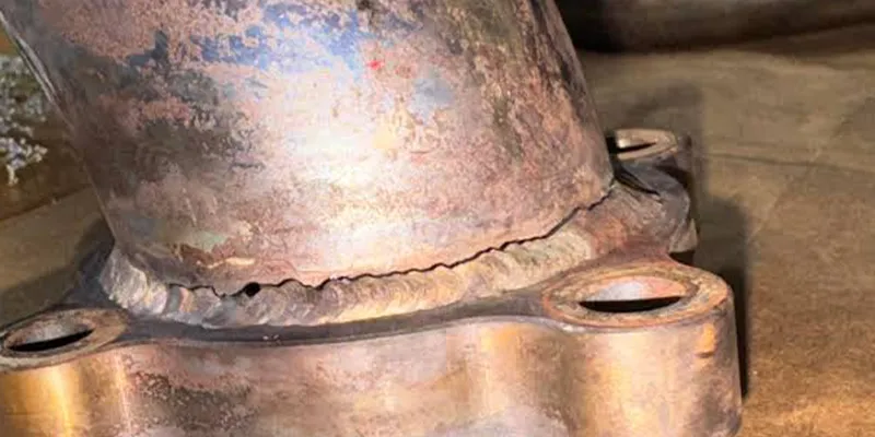
DDC is not centerline cracking. It runs along prior-austenite grain boundaries, is intergranular, and shows up in restrained, multipass joints and in fully-austenitic low-ferrite deposits. Because it appears on reheating, it is easy to confuse with reheat cracking - the distinguishing clue is timing and location: DDC follows the reheated grain structure of the weld/HAZ, while reheat cracking is linked to a discrete 600-850 C hold and to high residual stress in thick joints.
What Is Reheat (Stress-Relief) Cracking and Why Is 347 Notorious For It?
Reheat cracking initiates during a hold in the 600-850 C range - a stabilization anneal or a post-weld stress-relief heat treatment - and 347 is a classic offender because niobium carbides and nitrides re-precipitate during that hold, strengthening the grain interiors while weakening the boundaries under residual stress.
The mechanism is well documented on thick-wall TP347 pipe: large residual stress from heavy wall thickness, some retained ferrite at the grain boundaries, and re-precipitating chromium/niobium carbides, nitrides and oxides combine so that the boundary can no longer accommodate the strain and voids grow and link into cracks. The practical consequence is that post-weld heat treatment of 347 is a decision, not a reflex: a stabilization anneal may be warranted for corrosion or dimensional reasons, but it must be followed by reheat-crack inspection, and the hold temperature and time should be chosen with the residual-stress state in mind. This is the one mechanism where doing the 'safe' thing (stress relieving) can create the defect.
How Does the Niobium Stabilizer Drive 347 Weld Cracking?
Niobium is the common thread through all three cracking families - it suppresses ferrite (pushing the weld toward the crack-prone fully-austenitic mode) and it forms low-melting or embrittling precipitates at the levels used for stabilization, so the cure is to control ferrite and cleanliness around niobium, not to remove it.
The decisive parameter reported in the literature is a ratio of about Nb/2 divided by (30C + 50N): as that ratio rises, hot-cracking susceptibility rises. At the same time, the same niobium pins dislocations and grain boundaries at high temperature, giving 347 its creep strength above about 550 C. So niobium is simultaneously the reason to choose 347 and the reason its weld needs more respect than a 304L weld. The fabrication answer is a filler and procedure that retain a few percent of delta ferrite and keep impurities (P, S, Si, N) low, which the next two sections quantify.
Why Does Ferrite Number Matter So Much for 347 Weld Cracking?
Ferrite number is the single most controllable variable in 347 weld integrity - stay in FN 3-8 (some codes allow FN 4-10) and you defeat solidification and ductility-dip cracking; fall below FN 3 and cracking risk rises steeply, while pushing above FN 8-10 trades one risk (hot cracking) for another (sigma-phase embrittlement).
Below FN 3 the weld is effectively fully austenitic and fissuring is hard to avoid. At FN 6 or more, fissuring is normally eliminated. The catch for 347 is that niobium fights ferrite, so the ER347-class filler has to be chemistry-balanced (typically elevated chromium or balanced nickel) to hold the band - you cannot rely on the base metal to supply it.
Ferrite number: the crack-resistant window for 347 welds
| Ferrite Number band | Risk | Action |
|---|---|---|
| FN < 3 | High solidification / DDC risk (fully austenitic) | Increase Cr or reduce Ni in filler; requalify |
| FN 3-8 (target) | Crack-resistant; good balance | Hold this band; verify with gauge |
| FN 8-10 | Acceptable in some codes | Watch sigma-phase risk in hot service |
| FN > 10 | Sigma-phase embrittlement, magnetic response | Reduce Cr / raise Ni; rebalance chemistry |
How Do You Predict and Control Ferrite in 347 Welds Using WRC-1992?
Use the WRC-1992 constitution diagram - Creq = Cr + Mo + 0.7Nb and Nieq = Ni + 35C + 20N + 0.25Cu - to place the deposit on the ferrite map, and then verify the actual ferrite with a calibrated gauge, because dilution from the base and from preceding passes moves the real point.
The 0.7Nb term is the 347-specific twist: niobium directly lowers the ferrite potential, which is precisely the effect that makes 347 crack-sensitive.
A worked example - an ER347 deposit with about 19 percent Cr, 10 percent Ni, 0.8 percent Nb, 0.06 percent C and 0.06 percent N - gives Creq about 19.6 and Nieq about 13.3, a Creq/Nieq ratio near 1.5, sitting close to the austenite boundary and yielding only modest ferrite. That illustrates why 347 filler chemistry is a design choice. The map only sets the target; the weld's true ferrite is measured per ISO 8249 / AWS A4.2 on the actual deposit. The ASTM A312 TP347 pipe and TP347H pipe pages show where 347 weldments are used in practice.
How Do 347 and 321 Compare for Weldability?
Both are stabilized and both weld with ER347-class filler, but 347 is the more crack-sensitive of the two because niobium forms more harmful low-melting eutectics than titanium, while offering better high-temperature creep strength; 321 is slightly easier to weld but loses titanium through the arc, which is why ER347 is used on 321 too.
347 vs 321: weldability and cracking at a glance
| Aspect | 347 (Nb-stabilized) | 321 (Ti-stabilized) |
|---|---|---|
| Hot-cracking resistance | Good, but needs FN ~6+ | Slightly better than 347 |
| Stabilizer loss in arc | Negligible (Nb stable) | Ti can burn off (use ER347) |
| Preferred filler | ER347 / ER347Si | ER347 (not ER321) for welds |
| High-temp creep strength | Higher above ~550 C | Lower than 347 |
| Reheat-cracking tendency | Notable (Nb precipitation) | Less than 347 |
| Service temperature | Continuous to ~900 C | Continuous to ~870 C |
Which Filler Metal Should You Use for 347?
Weld 347 with a matching niobium-stabilized filler (ER347 or ER347Si for GTAW/GMAW, E347 for SMAW) so the deposit keeps the same stabilization and corrosion behavior, and switch to an overalloyed 309/309L or nickel-base filler only for dissimilar joints where dilution would otherwise create a crack-sensitive interface.

Fillers are not interchangeable. ER347 is used for both 347 and 321 base because titanium burns off a 321 filler in the arc while niobium survives. For 347-to-carbon-steel or 347-to-unstabilized-stainless joints, the first diluted layer must be protected with 309/309L or a nickel-base alloy (82/182, 625) and the procedure qualified under ASME Section IX. The Hastelloy C276 welding guide and the Inconel 625 welding guide show the same overalloy-the-first-layer logic for nickel alloys.
| Joint | Recommended filler | Why |
|---|---|---|
| 347 to 347 | ER347 / E347 (ER347Si for better wetting) | Matching Nb stabilization, retains corrosion behavior |
| 347 to 321 | ER347 | Ti burns off a 321 filler; ER347 covers both |
| 347 to carbon steel | 309 / 309L or Ni-base (82/182, 625) | Controls dilution, avoids brittle/crack-prone interface |
| 347 to unstabilized SS | 309/309L or Ni-base | Stops low-ferrite, corrosion-weak first layer |
How Does Welding Procedure Affect 347 Crack Susceptibility?
Heat input, interpass temperature and shielding gas are the procedure levers that move a 347 joint into or out of the cracking windows - control them and you control the risk; ignore them and even a good filler will crack.
Keep interpass temperature low (commonly below about 150 C) to minimize time in the sensitization band and to limit distortion from austenitic stainless's high thermal-expansion coefficient.
Control heat input so the weld does not dwell in the 600-900 C reheating window longer than necessary, especially on multipass joints where DDC initiates.
Purge the root with argon - never nitrogen, which is absorbed into the pool and worsens hot cracking in stabilized grades; verify the oxygen level at the vent, not just the number of purge volumes.
Keep the joint clean: carbon or oil pickup raises carbide and crack potential, and poor shielding causes nitrogen pickup.
Qualify and follow the WPS, and treat any deviation (wrong filler, high interpass, contaminated gas) as the first suspect when a crack appears.
Does 347 Need Post-Weld Heat Treatment, and Does That Cause Reheat Cracking?
347 normally does not need post-weld heat treatment because stabilization already prevents sensitization, but any 600-850 C hold - whether a stabilization anneal or a stress relief - can trigger reheat cracking in thick, restrained welds, so PWHT is a deliberate decision followed by crack inspection.
When a stress-relief heat treatment is mandated by the design code, the defense is to keep ferrite controlled, limit the hold time and temperature, or use a stabilization anneal in the 843-899 C band, and then inspect for intergranular cracking. If a crack is found only after PWHT, assume reheat cracking and change the heat-treatment decision rather than simply rewelding. The same PWHT trade-off is discussed for other stabilized alloys in the Inconel 625 heat-treatment notes.
What About Sensitization, Chloride Stress Corrosion, and Liquation Cracking?
347's stabilization largely eliminates sensitization (its main selling point), but it does nothing for chloride stress-corrosion cracking and it carries a fusion-line liquation-cracking mode - so a 347 failure investigation must rule in or out SCC and liquation, not assume every crack is hot cracking.
Sensitization is avoided because carbon is bound as niobium carbide, so chromium carbide does not precipitate at the grain boundaries in the 425-850 C band during normal welding. Chloride SCC, however, is a real risk above roughly 50-60 C wherever chlorides and tensile stress coexist, and 347 is poorly equipped for it - no molybdenum, PREN only about 17-19.
If a crack is intergranular and chloride-associated, treat it as SCC and fix the environment; the upgrade path runs through 316L, 904L or 254SMO / 6Mo. Liquation cracking appears right at the fusion line when NbC, phosphide/sulphide or sigma-austenite films at the grain boundaries melt during the peak thermal cycle; it is a HAZ-mode failure that good purification and ferrite control reduce but do not always remove.
How to Investigate a 347 Weld Crack?
1. Mark every crack on a sketch; note whether it is in the weld metal, the heat-affected zone, the fusion line, or the base metal, and whether it is transverse, longitudinal, branched or hairline.
2. Collect the WPS/PQR, filler grade, heat input, interpass temperature, purge method, joint restraint and any post-weld heat treatment or stabilization anneal applied.
3. Run dye penetrant (PT) and/or magnetic-particle (MT) to map surface cracks, and ultrasonic (UT) or radiography (RT) to find subsurface and underbead cracks before you cut.
4. Grind or section a representative crack, etch the cross-section, and note whether cracking is intergranular or transgranular, and how far it sits from the fusion line.
5. Examine under the optical or scanning microscope; measure the ferrite number with a calibrated ferrite gauge and look for the austenitic (crack-susceptible) versus ferritic-austenitic solidification mode.
6. Check the weld deposit chemistry (Cb/Nb, C, N, Si, P, S) and the dilution from the base or preceding passes; rule out carbon pickup from oils or nitrogen pickup from poor shielding.
7. Assign the crack to solidification cracking (during freezing), ductility-dip cracking (about 600-900 C on reheating), or reheat cracking (600-850 C during PWHT), using location, morphology and thermal history.
8. Remove the crack by controlled grinding, re-weld with a ferrite-controlled procedure, then re-inspect with the same NDE method that found it, and document the corrective action.
What Are the Corrective Actions Once the Mechanism Is Identified?
The repair is always 'remove the crack, re-weld with a ferrite-controlled procedure, re-inspect' - but the lever that actually prevents recurrence is the root-cause fix, which differs by mechanism: ferrite for hot cracking, dilution/filler for DDC-prone joints, and the PWHT decision for reheat cracking.
Mechanism to corrective action
| If the mechanism is | Root-cause fix | Repair |
|---|---|---|
| Solidification cracking | Raise FN into 3-8 (rebalance filler Cr/Ni); lower impurities | Grind out, re-weld with controlled ferrite, PT verify |
| Ductility-dip cracking | Reduce reheating; control interpass; keep ferrite | Remove intergranular cracks, re-weld, re-PT/UT |
| Reheat cracking | Change or skip PWHT; lower hold T/time; relieve restraint | Remove cracks, re-weld, inspect after any heat treatment |
| Liquation cracking | Purify; control heat input; ferrite at fusion line | Remove HAZ cracks, requalify procedure |
| Chloride SCC | Change environment or upgrade grade (316L/904L/6Mo) | Replace cracked section; address chlorides |
Frequently Asked Questions