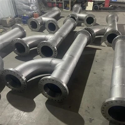
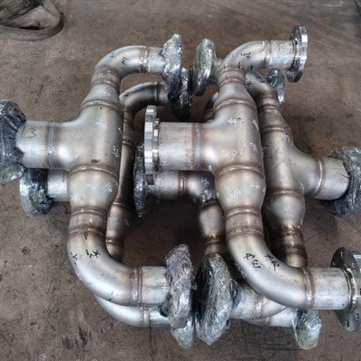
A furnace tray, grid, or support beam that was straight when it went in and has a visible belly after a few hundred heats is a familiar problem. The first reaction is often to blame the steel and ask for a better grade. Sometimes that is right. More often, the fixture is a good piece of 310S asked to carry more load, at a higher temperature, over a longer span than 310S can support. 310S is chosen for its oxidation resistance, not for its high-temperature strength, and that difference explains many sagging fixtures.
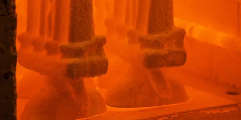
This guide shows how to separate the three families of cause (material, load, and design), gives the real strength numbers for 310S at furnace temperatures, and sets out a practical way to decide whether to redesign, change alloy, or simply replace.
Fixture sag is creep: slow, permanent deformation under steady load at high temperature. 310S resists scaling up to roughly 1,040–1,150°C depending on the producer's rating, but its creep strength is low: published values for 1% creep in 10,000 hours are about 10 MPa at 800°C and about 4 MPa at 900°C, far below its short-time tensile strength.
Raising the temperature by about 100°C roughly halves the stress it can carry. In practice, most sagging 310S fixtures are limited by load, span, and section design, with material problems (sigma phase, carburization, scale loss, wrong grade) as the secondary cause. Check the stress against the creep data first, then inspect the metal, then decide between redesign, a stronger alloy, or replacement.
Why Do 310S Furnace Fixtures Sag in Service?
Because at furnace temperatures steel flows slowly under constant load, a process called creep, and 310S has modest creep strength. The sag is the visible result of stress, temperature, time, and geometry combining, so it has a material cause, a load cause, and a design cause that usually act together.
A useful picture for non-specialists is stiff modeling clay: it holds its shape for a while, but under constant weight it slowly deforms, and it deforms faster when warm. Hot steel behaves the same way. At low temperature a loaded beam bends elastically and springs back. Above roughly half the melting temperature of the metal, it also creeps, and the deformation does not recover. Creep speeds up as temperature rises, as stress rises, and as the section thins, which is why a fixture that survived a hundred cycles can start to sag quickly.
|
Cause Family |
Examples |
Typical Signs |
|
Material |
Wrong or substituted grade, embrittlement by sigma phase, carburization or sulfur attack, scale loss, poor welds |
Cracking, brittle fracture, deep scaling, damage concentrated in one area or one batch |
|
Load and temperature |
Heavier or stacked loads, higher furnace temperature, hot spots, restrained expansion, rough handling |
Sag in all similar fixtures after a process change; worst at the hottest or most loaded positions |
|
Design |
Long unsupported span, thin section, weak orientation, no expansion allowance, loading at midspan |
Smooth, uniform bow at midspan; sag returns after replacement with the same design |
Table 1. The three cause families behind sagging furnace fixtures.
What Are 310S's Real Strength Limits at Furnace Temperatures?
310S has excellent oxidation resistance but low creep strength. At 900°C the stress that produces 1% creep in 10,000 hours is only about 4 MPa, and the stress that ruptures the metal in 10,000 hours is about 8.5 MPa, even though the short-time tensile strength at that temperature is over 100 MPa. Design for creep, not for tensile strength.
|
Temperature |
1% creep, 1,000 h (MPa) |
1% creep, 10,000 h (MPa) |
Rupture, 1,000 / 10,000 / 100,000 h (MPa) |
|
600°C |
100 |
90 |
170 / 130 / 80 |
|
700°C |
45 |
30 |
80 / 40 / 18 |
|
800°C |
18 |
10 |
35 / 18 / 7 |
|
900°C |
10 |
4 |
15 / 8.5 / 3 |
Table 2. Estimated average creep properties of 310S (EN 1.4845). Sources: Euro Inox / Edelstahl Rostfrei high-temperature stainless guide and a steel service supplier data sheet. Values are averages, not design allowables; another supplier sheet lists about 4 MPa for 10,000-hour rupture at 1,000°C.
Three points follow from these numbers.
First, creep strength falls fast with temperature: going from 800°C to 900°C cuts the 10,000-hour rupture strength from 18 to 8.5 MPa (about 53%) and the 1% creep limit from 10 to 4 MPa (about 60%). In other words, a rise of about 100°C roughly halves the stress the fixture can carry.
Second, short-time tensile numbers mislead: one data sheet lists a short-time tensile strength of about 135 MPa at 900°C, more than thirty times the 4 MPa creep limit.
Third, the oxidation rating is not a load rating. Producers rate 310S for oxidation up to about 1,040–1,150°C (for example 1,050°C for mildly cyclic service in one producer's range, and 1,150°C continuous in air in another's data sheet), but those limits describe scaling, not how much load the metal can carry. In an Outokumpu comparison test at 1,000°C, thin 1 mm rings of 310S and 314 collapsed under their own weight in 35 hours.
How Do You Tell a Material Cause From a Load or Design Cause?
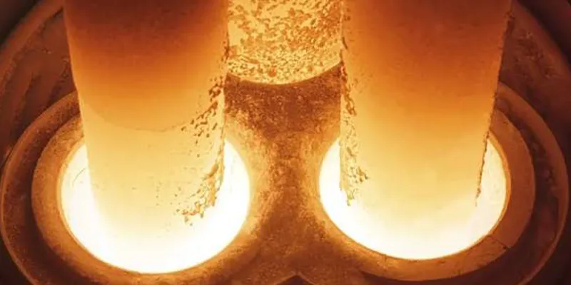
Work from the evidence: how the sag looks, what the metal looks like in cross-section, what the furnace actually did, and how sister fixtures behaved. A smooth bow at midspan in every similar fixture points to load or design; localized cracking, brittleness, or severe scaling points to material or atmosphere.
|
Observation |
Likely Cause Family |
How to Confirm |
|
Smooth bow at midspan in all similar fixtures |
Load or design (stress above the creep limit) |
Calculate stress and compare with Table 2; review span, section, and orientation |
|
Sag began after a process change (higher temperature, heavier charge) |
Load and temperature |
Compare furnace records before and after; thermocouple survey |
|
One fixture or one batch sagged; others fine |
Material (wrong grade, heat variation) or local hot spot |
Positive material identification and chemistry; check position in furnace |
|
Brittle cracks, little bending, break when handled cold |
Material (sigma phase embrittlement) |
Room-temperature bend or impact check; metallography |
|
Deep scale, thinned section, metal wasted away |
Material or atmosphere (oxidation, sulfur, carburization) |
Measure remaining section; look for carburized or sulfidized layer in cross-section |
|
Sag with buckling or twisting at restraint points |
Design (restrained expansion) |
Check expansion gaps and how the fixture is held |
|
Cracks at welds or supports |
Design or weld quality |
Inspect welds; check stress concentration at attachments |
Table 3. Diagnostic guide separating material, load, and design causes of sag.
A solid investigation records the following before the fixture is scrapped: the sag measured against a straight edge or string line at several points, the remaining thickness compared with the original, the operating temperature record and the position of the fixture in the furnace, the weight and arrangement of the load, and a cross-section examined under a microscope. Microscopy can show scale penetration, a carburized or sulfidized layer, and the grain boundary damage (voids and cracks) typical of long-term creep.
Which Material Problems Make 310S Sag or Fail Early?
The main material problems are sigma phase embrittlement after long exposure at about 650–900°C, attack by carburizing or sulfur-bearing atmospheres, loss of section to scale, and use of the wrong grade. Several of these cause cracking or thinning rather than sag, but all of them raise the stress in the remaining metal and accelerate creep.
|
Material Problem |
What Happens |
Evidence and Remedy |
|
Sigma phase embrittlement |
A hard, brittle phase forms in high-chromium austenitic steels in about 650–900°C, reducing ductility |
Producer data: 310 is prone to sigma in this range; solution annealing at about 1,040–1,150°C then rapid cooling is recommended to restore ductility after each 1,000 hours above 650°C |
|
Carbide precipitation |
Carbides form at grain boundaries in about 425–860°C |
Mainly affects aqueous corrosion after cooling; often tolerated if the metal cycles above and below the range |
|
Carburization or sulfidation |
Carbon or sulfur from the atmosphere enters the metal, embrittles it, and degrades oxidation resistance |
Reducing sulfide atmospheres need a more resistant alloy (a producer data sheet points to 253 MA); higher-nickel alloys resist carburization better |
|
Scale growth and spalling |
Oxide grows and flakes off during thermal cycling, thinning the load-bearing section |
A creep analysis of refractory anchors found oxidation thickness loss cut predicted life from about 30,000 hours to about 8,000 hours |
|
Wrong or mixed grade |
304 or 309 substituted for 310S, or an unspecified lean grade |
Check with positive material identification and certificates; 309 and 310 differ in creep and oxidation limits |
|
Poor welds |
Hot cracking, porosity, or weld metal with lower strength than the base |
Inspect and qualify welding procedure and filler for the service temperature |
Table 4. Material problems that shorten the life of 310S fixtures.
It is worth noting how sigma phase works in practice: it mainly shows up as brittle cracking when the fixture is cold or handled, not as extra sag. But a fixture that has been through years of cycling in the sigma range can also have lost the ductility that lets it tolerate small deformations without cracking, so it is a risk factor, not just a symptom.
How Do Temperature and Load Drive Sag?
Stress and temperature drive creep exponentially. A small rise in metal temperature or a modest increase in load can multiply the sag rate, so even small process changes matter. Calculate the actual stress in the fixture and compare it with the 1% creep limit at the real metal temperature.
Load comes from the product weight, stacking and arrangement of parts, the weight of the fixture itself, thermal gradients, and the restraint of thermal expansion. Austenitic stainless steels expand about 17 to 19 millionths per degree Celsius at furnace temperatures (typical published values are about 17 at 400°C and 17.5 at 600°C), so a 1.2 meter bar heated from room temperature to 900°C grows by roughly 19 mm. If its ends are held, it cannot grow, so it buckles or yields, and each heat cycle can ratchet the deformation. That looks like sag but is caused by restraint, not weight.
A worked screening example shows how quickly stress exceeds the creep limit. Consider a 310S bar 40 mm by 10 mm, simply supported over 600 mm, carrying a uniformly distributed load of about 100 kg (1.64 N/mm). The peak bending stress is wL²/8 divided by the section modulus Z. The results below are elastic screening values, not a design calculation. In real bending, creep redistributes stress, so the elastic peak overstates the long-term stress somewhat, but the order of magnitude is what matters.
|
Case (310S bar, 1.64 N/mm load) |
Section modulus Z (mm³) |
Peak bending stress (MPa) |
Versus 1% creep in 10,000 h |
|
A. 600 mm span, 40 mm wide laid flat (10 mm deep) |
667 |
About 110 |
Far above 10 MPa (800°C) and 4 MPa (900°C) |
|
B. 600 mm span, on edge (40 mm deep, 10 mm wide) |
2,667 |
About 28 |
About 2.8 times the 800°C limit, 7 times the 900°C limit |
|
C. 300 mm span, on edge (40 mm deep) |
2,667 |
About 6.9 |
Below 800°C limit; above 900°C limit |
|
D. 300 mm span, on edge, 60 mm deep |
6,000 |
About 3.1 |
Below both limits |
Table 5. Worked screening example: stress in a loaded 310S bar versus the 1% creep limits of Table 2 (10 MPa at 800°C and 4 MPa at 900°C for 10,000 hours).
The lesson is practical: in case A, orientation and span alone put the bar at more than ten times the allowable creep stress. Turning the bar on edge cuts the stress by a factor of four, and halving the span cuts it by a further factor of four. These design changes are free; changing the alloy is not.
Which Design Features Cause Sag Even When the Material Is Good?
The biggest design factors are span, section depth, and orientation. Stress rises with the square of the span and falls with the square of the section depth, and elastic deflection rises with the fourth power of the span, so long, shallow, flat-laid members are the most prone to sag.
|
Design Change (same load per length) |
Effect on Peak Stress |
Effect on Deflection |
|
Double the section depth (on edge) |
Divided by 4 |
Divided by 8 |
|
Double the width (same depth) |
Divided by 2 |
Divided by 2 |
|
Halve the span |
Divided by 4 |
Divided by 16 |
|
Rotate a flat bar 90° to stand on edge (40 × 10 mm) |
Divided by 4 |
Divided by 64 |
|
Double the span |
Multiplied by 4 |
Multiplied by 16 |
Table 6. Effect of simple geometry changes on stress and elastic deflection of a simply supported beam under uniform load. Creep sag follows the stress, so the stress column is the guide.
Other design features that cause sag include loading at the center of a long span instead of near the supports, supports spaced too far apart, thin plate trays with no ribs or flanges, asymmetric heating that makes the top hotter than the bottom, welds placed at points of maximum stress, and attachments that restrain expansion. A fixture can be redesigned with the same alloy by adding supports, deepening the section, adding stiffening ribs or flanged edges, shortening spans, and allowing expansion with slotted holes or free ends.
When Should You Change Alloy Instead of Redesigning?
Change alloy when the stress, after reasonable redesign, is still above the creep limit of 310S at the real metal temperature, or when the atmosphere (carburizing, sulfur-bearing) attacks 310S. Alloys with higher creep strength or higher nickel content can carry more load or resist the atmosphere, at a higher material cost.
Published comparisons show where the options stand. A heat-resistant alloy producer reports that 253 MA has creep-rupture strength about double that of 310 and 309 stainless at 870°C (1,600°F), and that it has replaced 310 in some cyclone and heat treatment applications. In the same producer's table of average stress to rupture at 927–1,093°C (1,700–2,000°F), 310 stainless is listed at about 4.6 to 6.5 MPa, 253 MA at about 4.7 to 11.4 MPa, Alloy 800H at up to about 13 MPa, and Alloy 601 at about 4.3 to 8.3 MPa, with the exact temperature for each entry given in the original table.
For carburizing atmospheres and repeated thermal cycling, higher-nickel alloys such as 330 are widely used for baskets and fixtures, and heavy-section cast alloys (HK and HP types) are common for the highest loads.
|
Alloy |
Strength and Resistance Features |
Considerations |
|
310S (S31008, EN 1.4845) |
Excellent oxidation resistance; moderate creep strength |
Sigma phase risk at 650–900°C; limited creep strength; check the atmosphere |
|
253 MA (S30815) |
Higher creep strength than 310 (about double at 870°C per one producer); good oxidation resistance with silicon, nitrogen, and rare earth additions |
Often used where strength and cost matter; better in reducing sulfide atmospheres per a producer data sheet |
|
Alloy 800H/HT |
Higher stress-rupture strength than 310 in published tables |
Relies on solution annealing and carbon and aluminum control; check availability and cost |
|
Alloy 330 (about 35% Ni) |
Higher nickel gives better carburization and thermal shock resistance |
Widely used for baskets and trays in heat treating; creep strength is not its main advantage |
|
Alloy 601 and other nickel alloys |
High oxidation resistance and good strength at very high temperature |
Cost; welding and supply; confirm suitability for the atmosphere |
|
Cast HK / HP |
Heavy-section creep strength for the highest loads |
Cast construction; different design and repair rules |
Table 7. Alloy options for furnace fixtures that sag. Selection depends on temperature, load, atmosphere, and cost. Values and comparisons come from published producer data and should be confirmed for the specific application.
How Do You Repair, Straighten, or Replace a Sagged Fixture?
Replace or redesign rather than straighten, unless the sag is small and the metal sound. Creep damage accumulates inside the metal as voids and cracks, so straightening does not restore life, and a fixture with sigma phase embrittlement can crack when forced.
|
Condition |
Typical Action |
Reason |
|
Small sag within the allowed limit, metal sound |
Return to service with monitoring |
No damage beyond normal creep; record the sag rate |
|
Moderate sag, no cracks, ductile when tested |
Redesign or replace at the next opportunity; avoid repeated straightening |
Creep damage continues; sag will return |
|
Cracks, brittle behavior, or deep scaling |
Replace |
Embrittlement or section loss; straightening can fracture the part |
|
Sag in every fixture after a process change |
Review load and temperature; redesign or change alloy |
Operating conditions exceed the design basis |
|
Repeated sag at restraint points |
Provide expansion allowance |
Restrained expansion is driving the deformation |
Table 8. Repair, replace, or redesign guide for sagged furnace fixtures.
Set a sag limit and an inspection interval, record the number of cycles and the operating temperature, and measure sag at the same positions each time so the trend is visible. A sag rate that is increasing indicates accelerating creep and signals the end of useful life. If solution annealing is used to restore ductility after long exposure in the sigma range, it should be done under controlled conditions with distortion in mind.
How Should You Specify Replacement 310S Fixtures to Prevent Recurrence?
Specify the design temperature, atmosphere, and load, then state the grade and standard, the section and span limits, the expansion provisions, and an inspection plan. A purchase order that says only "310S" leaves the actual cause of sag unaddressed.
|
Specification Item |
What to State |
|
Operating conditions |
Maximum metal temperature, atmosphere (air, endothermic, carburizing, sulfur-bearing), number and rate of thermal cycles |
|
Load |
Weight and arrangement of the product, stacking, and any dynamic loads |
|
Material |
Grade and product standard (for example ASTM A240 UNS S31008, EN 1.4845), annealed condition, and mill certificate with heat number |
|
Geometry |
Maximum unsupported span, section depth, orientation, ribs or flanges, support positions |
|
Expansion |
Slotted holes or free ends; no rigid restraint of both ends |
|
Welding |
Qualified procedure, filler suitable for the service temperature, inspection of welds |
|
Acceptance |
Allowable sag and a measurement method |
|
Inspection plan |
Measure sag and thickness after a stated number of cycles; record temperature |
Table 9. Specification checklist for replacement furnace fixtures.
Frequently Asked Questions
Why do 310S furnace fixtures sag?
Because 310S creeps slowly under load at high temperature. Published data show a 1% creep limit of about 4 MPa for 10,000 hours at 900°C, so long spans, thin sections, and heavy loads quickly exceed what the metal can carry.
What is the maximum temperature for 310S?
Producers rate 310S for oxidation resistance up to about 1,040–1,150°C, depending on the source and on whether service is continuous or cyclic. That is an oxidation limit, not a load limit; creep strength is much lower at those temperatures.
Is the sag caused by bad material?
Not usually. Most sag is caused by load, span, and section design. Material problems such as sigma phase, carburization, scale loss, or the wrong grade are secondary and can be confirmed by metallography and positive material identification.
What is sigma phase in 310S?
A hard, brittle phase that forms in high-chromium austenitic stainless steels in about 650–900°C. It reduces ductility and can be dissolved by solution annealing at about 1,040–1,150°C followed by rapid cooling.
How can I stop a fixture from sagging without changing the alloy?
Shorten the span, add supports, deepen the section, stand flat bars on edge, spread the load, and avoid restraining expansion. Halving the span cuts stress by four times, and doubling the section depth also cuts it by four times.
When should I switch to 253 MA or a nickel alloy?
When the stress after redesign is still above the creep limit of 310S at the real metal temperature, or when the atmosphere attacks 310S. 253 MA has about double the creep-rupture strength of 310 at 870°C per one producer, and higher-nickel alloys resist carburization better.