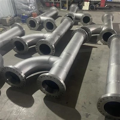
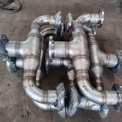
Incoloy 800H (UNS N08810) allowable stresses for ASME Section I and Section VIII Division 1 are published in Section II (Materials), Part D (Properties).
Section I (power boilers) construction with 800H is permitted to 1500 °F (816 °C); Section VIII Division 1 construction is permitted to 1800 °F (982 °C).
Section VIII Division 2 coverage for 800H is much narrower - only to 800 °F (427 °C).
Incoloy 800HT (UNS N08811) carries higher allowable stresses than 800H between 1100 °F and 1650 °F, and every 800HT heat also satisfies the 800H requirements.
800H must have 0.05-0.10 % carbon and an ASTM No. 5 or coarser grain size; plain Incoloy 800 (UNS N08800) has no carbon floor and no grain-size requirement.
In the creep range, ASME sets the allowable stress from the 100,000-hour rupture strength. The rupture criterion was raised from 62.5 % to 67 % in 1969.
Representative 100,000-hour rupture strength for 800H/800HT falls from 13.0 ksi (90 MPa) at 1200 °F to 0.8 ksi (5.5 MPa) at 1800 °F.
How to establish the ASME allowable stress for an 800H component

- Confirm the UNS number and the grain size on the MTR. Verify UNS N08810 (800H) or N08811 (800HT), carbon in the 0.05-0.10 % band, and an average grain size of ASTM No. 5 or coarser. Without these, the higher creep-range allowable stresses do not apply.
- Confirm which Code book governs the component. Power boiler parts follow ASME Section I; pressure vessels follow Section VIII Division 1. Both read their design stress from Section II, Part D, but Section I stops at 1500 °F (816 °C) while Section VIII Division 1 extends to 1800 °F (982 °C).
- Read the design stress at the design temperature, not at ambient. 800H loses roughly half of its allowable stress between 1100 °F and 1400 °F. Always interpolate the table at the metal design temperature used in the calculation.
- Check whether time-dependent or time-independent rules control. Below roughly 1100 °F (593 °C) tensile and yield strength set the allowable. Above that, creep rate and 100,000-hour rupture strength take over and the allowable drops steeply.
- Apply the joint-efficiency and wall-thickness rules of the governing book. Use the Section I or Section VIII Division 1 formula with the allowable stress you just read, then re-check the temperature ceiling for oxidation, carburisation and sigma-phase exposure, which the Code tables do not cover.
Incoloy 800H is one of the few alloys where the number on the mill certificate and the number in the design calculation are joined by a chain of logic that most engineers never see. A creep-rupture test running for 100,000 hours - more than eleven years - produces a single point on a graph. ASME then divides that point by a safety factor, compares it against two other creep criteria, and publishes the result as one line in a table. That line decides how thick your reformer tube has to be. This article opens the whole chain: the test data, the Code rules, the published temperatures, and the practical consequences for wall thickness, grade selection and procurement.
What Is Incoloy 800H, and Why Does the "H" Change the Allowable Stress?
The "H" is a purchase specification, not a marketing label. It guarantees a carbon floor of 0.05-0.10 % and an average grain size of ASTM No. 5 or coarser, and only material meeting both conditions earns the elevated-temperature allowable stresses in the ASME tables. Buy plain Incoloy 800 and none of those values apply.
The reason is microstructural rather than chemical. All three grades of the 800 series share essentially the same base analysis - 30.0-35.0 % nickel, 19.0-23.0 % chromium, 39.5 % minimum iron - so at room temperature they behave almost identically. The separation appears only when time and temperature enter the picture. Creep in an austenitic alloy is largely grain-boundary sliding: the grains slide past one another along their boundaries, and the more boundary area there is, the faster the deformation. Coarse grains mean less boundary area per unit volume, so they creep more slowly. Carbon helps in a second way. During the high-temperature anneal it precipitates as grain-boundary carbides that pin those boundaries and resist sliding.
ASME treats this seriously because the code table is a statistical product, not a single test result. To publish an allowable stress in the time-dependent range, the committee must have a multi-heat rupture database tight enough for a lower-bound regression to be defensible. Fine-grain, low-carbon heats scatter too widely to support that regression, so 800 drops out of the elevated-temperature table while 800H and 800HT stay in it.
Table 1 - Limiting chemical composition and grain size: Incoloy 800, 800H and 800HT
|
Element / requirement |
800 (UNS N08800) |
800H (UNS N08810) |
800HT (UNS N08811) |
|
Nickel |
30.0-35.0 % |
30.0-35.0 % |
30.0-35.0 % |
|
Chromium |
19.0-23.0 % |
19.0-23.0 % |
19.0-23.0 % |
|
Iron |
39.5 min. |
39.5 min. |
39.5 min. |
|
Carbon |
0.10 max. |
0.05-0.10 % |
0.06-0.10 % |
|
Aluminium |
0.15-0.60 % |
0.15-0.60 % |
0.25-0.60 % |
|
Titanium |
0.15-0.60 % |
0.15-0.60 % |
0.25-0.60 % |
|
Aluminium + titanium |
0.30-1.20 % |
0.30-1.20 % |
0.85-1.20 % |
|
ASTM grain size |
Not specified |
No. 5 or coarser |
No. 5 or coarser |
Source: Special Metals technical bulletin for INCOLOY alloy 800H/800HT, Table 1. Note that the 800HT composition window sits entirely inside the 800H window, which is why every 800HT heat can be certified to both UNS numbers. For specific orders some purchasers restrict the aluminium and titanium in 800H to 0.4-0.7 % for service between 1000 °F and 1400 °F (540-760 °C), where intermediate-temperature ductility matters more than maximum rupture strength.
How Does ASME Convert Creep-Rupture Data Into an Allowable Stress?
In the time-dependent range ASME takes the lowest of three values - 100 % of the stress producing a creep rate of 0.01 % per 1,000 hours, 67 % of the average stress causing rupture in 100,000 hours, and 80 % of the minimum stress causing rupture in 100,000 hours. The published allowable is whichever of these is smallest.

This three-way comparison is the whole engine behind the elevated-temperature table. The first criterion protects against excessive deformation: a vessel that stretches has failed functionally even if it has not broken. The second and third protect against rupture, using both the average and the lower bound of the data set so that a single optimistic heat cannot inflate the allowable. The 67 % rupture factor has a history worth knowing - it was raised from 62.5 % in 1969 once the committee judged the growing rupture database to be reliable enough, and the minimum tensile strength curve was raised by 10 % at the same time.
Table 2 - How ASME sets allowable stress: time-independent versus time-dependent rules
|
Basis |
Rule |
What it protects against |
|
Tensile strength |
One third (1/3.5) of tensile strength at temperature |
Bursting under short-term overload |
|
Yield strength |
Two thirds (2/3) of 0.2 % yield strength at temperature |
Gross plastic deformation |
|
Creep rate |
100 % of the stress giving 0.01 % creep per 1,000 hours |
Excessive deformation over the design life |
|
Rupture (average) |
67 % of the average stress causing rupture in 100,000 hours |
Long-term rupture across the production population |
|
Rupture (minimum) |
80 % of the minimum stress causing rupture in 100,000 hours |
Long-term rupture in the weakest heat tested |
Two practical points follow. First, the allowable stress is always the minimum of the applicable rules, so the criterion that governs can change with temperature - and knowing which one governs tells you which failure mode you are designing against. Second, the 100,000-hour reference life is roughly 11.4 years of continuous service. It is a design convention, not a predicted service life: components routinely run for far longer because the allowable already carries a substantial margin.
Where Are the 800H Design Stresses Published, and Which Code Book Governs Your Part?
Every governing book reads its 800H design stress from ASME Section II (Materials), Part D (Properties), but they do not all allow the same maximum temperature. Section I permits service to 1500 °F (816 °C), Section VIII Division 1 to 1800 °F (982 °C), Section VIII Division 2 only to 800 °F (427 °C), and Section III nuclear construction is handled separately.
This is the single most useful thing to understand about 800H code data, because it means the phrase "boiler code allowable stress" and "pressure vessel allowable stress" usually describe the same number. The distinction that matters is not the value, it is the ceiling. A power boiler part made from 800H is capped at 1500 °F (816 °C) regardless of how much strength the alloy retains above that, while a Section VIII Division 1 vessel may be designed to 1800 °F (982 °C).
Table 3 - ASME coverage for Incoloy 800H (UNS N08810)
|
Code book |
Where the design stress comes from |
Maximum permitted temperature |
Additional reference |
|
Section I (power boilers) |
Section II, Part D |
1500 °F (816 °C) |
Code Case 1325 |
|
Section VIII, Division 1 |
Section II, Part D |
1800 °F (982 °C) |
Code Case 1983 |
|
Section VIII, Division 2 |
Section II, Part D (Div. 2 table) |
800 °F (427 °C) |
- |
|
Section III, Class 1 |
Section II, Part D (Div. 2 table) |
Per Code Case |
N-201, N-253, N-254 |
|
Section III, Class 2 |
Section II, Part D (Div. 1 table) |
Per Code Case |
N-201, N-253, N-254 |
Source: Special Metals technical bulletin, ASME Boiler and Pressure Vessel Code section. One caution that applies to every row: ASME Code Cases are living documents. Cases 1325, 1983 and the 800HT case 1987 are periodically revised, incorporated into the Code books, or annulled once incorporation is complete. Before you finalise any design, confirm both the current status of the case and the edition of Section II, Part D specified in your project.
If you are sourcing material for Section I or Section VIII work, the product hub for Incoloy 800H plate, pipe and bar lists the ASTM and ASME specifications we normally supply against, and the Incoloy 800HT grade page covers the higher-allowable UNS N08811 option.
What Do the Representative Creep-Rupture Data for 800H/800HT Actually Show?
Rupture strength falls by more than an order of magnitude across the practical design window. Representative 100,000-hour rupture strength drops from 13.0 ksi (90 MPa) at 1200 °F (650 °C) to 0.8 ksi (5.5 MPa) at 1800 °F (980 °C) - a sixteenfold reduction for a 600 °F rise in temperature.

That collapse is the whole reason high-temperature design is a different discipline from room-temperature design. A pressure vessel designed at ambient conditions might see its allowable stress vary by 20 % across its whole operating envelope. An 800H component spanning 1200 °F to 1800 °F sees it vary by 1,500 %. Everything about the design - wall thickness, support spacing, thermal-expansion allowances, tube count - is driven by the hottest point in the system.
Table 4 - Representative rupture strength of INCOLOY alloys 800H/800HT (ksi / MPa)
|
Temperature |
10,000 h |
30,000 h |
50,000 h |
100,000 h |
|
1200 °F (650 °C) |
17.5 / 121 |
15.0 / 103 |
14.0 / 97 |
13.0 / 90 |
|
1300 °F (705 °C) |
11.0 / 76 |
9.5 / 66 |
8.8 / 61 |
8.0 / 55 |
|
1400 °F (760 °C) |
7.3 / 50 |
6.3 / 43 |
5.8 / 40 |
5.3 / 37 |
|
1500 °F (815 °C) |
5.2 / 36 |
4.4 / 30 |
4.1 / 28 |
3.7 / 26 |
|
1600 °F (870 °C) |
3.5 / 24 |
3.0 / 21 |
2.8 / 19 |
2.5 / 17 |
|
1700 °F (925 °C) |
1.9 / 13 |
1.6 / 11 |
1.4 / 10 |
1.2 / 8.3 |
|
1800 °F (980 °C) |
1.2 / 8.3 |
1.0 / 6.9 |
0.9 / 6.2 |
0.8 / 5.5 |
Source: Special Metals technical bulletin, Table 7 - Representative Rupture-Strength Values. Read the second half of that title carefully. These are representative, or typical, values. ASME does not use them directly; it uses lower-bound regressions over the full multi-heat database, which is why the tabulated Code allowable is normally below anything you calculate from this table. What the table is good for is shape: it shows how quickly strength is lost, how little extra life you buy by unloading a component, and where the practical temperature ceiling sits.
One more observation from the same table that surprises people. Moving from 50,000 hours to 100,000 hours - doubling the design life - costs only about 7 % of allowable stress at 1200 °F. Moving from 1600 °F to 1700 °F - a 6 % rise in absolute temperature - costs more than 50 %. Temperature dominates life far more than target life does.
What Allowable Stress Does That Rupture Data Imply at Each Temperature?
Applying the Code's own 67 %-of-average-rupture criterion to the representative 100,000-hour data gives indicative design stresses of about 8.7 ksi (60 MPa) at 1200 °F falling to about 0.54 ksi (3.7 MPa) at 1800 °F. The values actually tabulated in Section II, Part D are normally lower still, because ASME regresses the lower bound of the full database rather than typical results.
It is worth being explicit about why we show a derived column at all. Most published articles reproduce a code table without saying where it came from, which leaves the reader unable to sanity-check a number or interpolate between temperatures. Showing the derivation makes the table auditable: if you know the rupture strength and you know the criterion, you can reconstruct the allowable and see immediately which rule is controlling. The table below is labelled indicative for a reason - use it to understand the shape of the curve and to catch gross errors, then read the binding number from the code edition your project specifies.
Table 5 - Indicative design stress for 800H derived from representative rupture data using the 67 % rupture criterion
|
Temperature |
Representative 100,000 h rupture strength |
Indicative design stress (0.67 x rupture) |
Expected position vs. Code table |
|
1200 °F (650 °C) |
13.0 ksi (90 MPa) |
8.7 ksi (60 MPa) |
Code value typically below |
|
1300 °F (705 °C) |
8.0 ksi (55 MPa) |
5.4 ksi (37 MPa) |
Code value typically below |
|
1400 °F (760 °C) |
5.3 ksi (37 MPa) |
3.6 ksi (24 MPa) |
Code value typically below |
|
1500 °F (815 °C) |
3.7 ksi (26 MPa) |
2.5 ksi (17 MPa) |
Section I temperature ceiling |
|
1600 °F (870 °C) |
2.5 ksi (17 MPa) |
1.7 ksi (11 MPa) |
Section VIII Div. 1 only |
|
1700 °F (925 °C) |
1.2 ksi (8.3 MPa) |
0.80 ksi (5.5 MPa) |
Section VIII Div. 1 only |
|
1800 °F (980 °C) |
0.8 ksi (5.5 MPa) |
0.54 ksi (3.7 MPa) |
Section VIII Div. 1 ceiling |
NOTE: These derived values are an educational reconstruction from producer representative data, not Code values. ASME Section II, Part D remains the only binding source for design. Always confirm the edition, the UNS number, the product form and the heat-treatment condition before you use any number in a calculation.
Why Does the Allowable Stress Collapse Above About 1100 °F (593 °C)?
Because the governing rule changes. Below roughly 1100 °F (593 °C) the allowable is set by tensile and yield strength, which decay slowly with temperature. Above it, creep and rupture take over, and rupture strength decays roughly exponentially, so the allowable falls away far faster than the tensile curve would suggest.

The tensile data make the contrast concrete. Tensile strength for 800H/800HT falls from about 77 ksi at room temperature to about 32 ksi at 1400 °F - a factor of 2.4. Rupture strength over the same span falls by a factor of roughly fifteen. Yield strength behaves differently again: it stays remarkably flat, around 14-17 ksi, across the whole 1000-1600 °F band. If you designed only against yield, you would conclude that 800H is essentially unaffected by temperature, and that conclusion would be dangerously wrong in sustained service.
Table 6 - Typical tensile properties of INCOLOY alloys 800H/800HT at temperature
|
Temperature |
Tensile strength |
0.2 % yield strength |
Elongation |
|
70 °F (20 °C) |
77 ksi (531 MPa) |
29 ksi (200 MPa) |
52 % |
|
1000 °F (540 °C) |
63.5 ksi (438 MPa) |
16.5 ksi (114 MPa) |
51 % |
|
1200 °F (650 °C) |
55.7 ksi (384 MPa) |
14.8 ksi (102 MPa) |
50 % |
|
1400 °F (760 °C) |
32.3 ksi (223 MPa) |
14.4 ksi (99 MPa) |
78 % |
|
1600 °F (870 °C) |
18.6 ksi (128 MPa) |
11.6 ksi (80 MPa) |
120 % |
|
1800 °F (980 °C) |
10.2 ksi (70 MPa) |
8.9 ksi (61 MPa) |
120 % |
Two clues hide in that table. The first is the elongation: it rises from 50 % to 120 % between 1200 °F and 1600 °F. That is not the alloy getting more ductile in any useful sense - it is the specimen creeping during the test itself, accumulating strain that the test machine records as elongation. The second is the divergence between tensile and yield: at 1800 °F they are within 1.3 ksi of each other. Strength reserve is vanishing, which is exactly the regime where time-dependent rules must take over.
Which Criterion Governs: Creep Rate or Rupture?
For 800H, the rupture criteria govern over most of the practical design window, and the creep-rate criterion is usually not the limiting one. That matters because it tells you the failure mode you are designing against is rupture, not excessive deformation.
You can check this without a code book. The creep-rate criterion uses a rate of 0.01 % per 1,000 hours, which is 1 x 10^-5 % per hour. Published minimum-creep-rate data for the alloy are often quoted at 1 x 10^-4 % per hour - ten times faster - and give 6.0 ksi at 1400 °F and 1.05 ksi at 1800 °F. Creep rate scales with stress to a power of roughly five to seven at these temperatures, so reducing the rate by a factor of ten requires cutting the stress by a factor of about 1.4 to 1.5. That puts the creep-rate-limited stress near 4 ksi at 1400 °F and near 0.7 ksi at 1800 °F - both above the rupture-derived values in Table 5. Rupture wins.
The practical implication is that an 800H part that reaches its design life is far more likely to crack than to sag. Inspection programmes for reformer and cracker tubing therefore prioritise crack detection - dye penetrant, ultrasonic and replication - over dimensional survey, and they concentrate on weld heat-affected zones and on the hottest sections of the tube.
How Do You Extrapolate Creep-Rupture Life With the Larson-Miller Parameter?
The Larson-Miller parameter collapses temperature and time into one number, so a 1,000-hour test can predict 100,000-hour behaviour. For 800H/800HT the relationship is P = (T + 460) x (22.93 + log t) x 10^-3, with T in °F and t in hours.
The logic is that creep is thermally activated: raising the temperature speeds up the same damage mechanisms that running longer would produce, so temperature and time are interchangeable to a good approximation. In practice you calculate P for your service temperature and target life, then read the corresponding stress from the alloy's Larson-Miller master curve.
The method is genuinely useful, and genuinely easy to misuse. Rupture data scatter by a factor of about two in life at a fixed stress, so any single extrapolation should be treated as an estimate with a band around it rather than a prediction. The parameter also assumes a single deformation mechanism operates across the range; if the mechanism changes - as it can when precipitation coarsens over decades - the extrapolation drifts.
Use it for interpolation, screening and remaining-life ranking across a furnace. Do not use it to justify pushing a component above the Code allowable stress.
Incoloy 800H vs 800HT vs 800: Which Allowable Stress Does Your MTR Actually Support?
Your mill test report decides, not your drawing note. 800HT carries the highest allowable stresses between 1100 °F and 1650 °F; 800H is next; plain 800 does not have Code-listed creep-range allowable stresses at all. If the MTR does not show the carbon band and the grain size, you do not have 800H regardless of what the purchase order said.
Table 7 - Qualification matrix: what each grade must demonstrate
|
Requirement |
800 (N08800) |
800H (N08810) |
800HT (N08811) |
|
Carbon band |
No minimum |
0.05-0.10 % |
0.06-0.10 % |
|
Aluminium + titanium |
0.30-1.20 % |
0.30-1.20 % |
0.85-1.20 % |
|
Grain size |
Not specified |
ASTM No. 5 or coarser |
ASTM No. 5 or coarser |
|
Final anneal |
Per specification |
High-temperature anneal producing coarse grain |
2100 °F (1149 °C) minimum |
|
Creep-range Code allowable |
Not listed |
Yes - Section I to 1500 °F, Section VIII Div. 1 to 1800 °F |
Yes - higher than 800H from 1100-1650 °F |
|
Dual certification |
No |
800H only |
Meets both N08811 and N08810 |
|
Best-fit service |
Below about 1100 °F, thermal cycling |
Sustained pressure, 1100-1500 °F |
Long-term service, 760-980 °C |
The dual-certification point deserves emphasis because it is routinely misread. Because the 800HT composition window sits entirely inside the 800H window, an 800HT heat can always be certified as 800H as well. The reverse is false: a heat meeting only N08810 cannot be certified as 800HT unless it also satisfies the additional carbon, aluminium-plus-titanium and heat-treatment requirements. So if your design was calculated on 800HT allowable stresses, the MTR must show N08811 - an 800H-only certificate forces you back to the lower values.
Our grade pages for Incoloy 800, Incoloy 800H and Incoloy 800HT set out the full specification coverage for each, and this guide to 800HT goes deeper on the UNS N08811 requirements.
How Does Allowable Stress Translate Into Pipe Wall Thickness?
Wall thickness scales inversely with allowable stress, so the collapse in allowable stress above 1100 °F is paid for directly in steel. In the worked example below, moving the design temperature from 1200 °F to 1600 °F quintuples the required wall - and quintuples the tube weight, the weld volume and the material cost for the same pressure.

The example uses the standard pressure-design form t = P x D / (2S + 0.8P) for a seamless tube with a joint efficiency of 1.0 and a Y coefficient of 0.4. Take a 4.000 in outside diameter reformer tube at 500 psi internal design pressure.
Table 8 - Worked example: required wall thickness versus design temperature (4.000 in OD, 500 psi, seamless, E = 1.0, Y = 0.4)
|
Design temperature |
Indicative allowable stress S |
Calculated wall thickness |
Relative tube weight |
|
1200 °F (650 °C) |
8.7 ksi (60 MPa) |
0.112 in (2.8 mm) |
1.0x (baseline) |
|
1400 °F (760 °C) |
3.6 ksi (24 MPa) |
0.263 in (6.7 mm) |
2.3x |
|
1600 °F (870 °C) |
1.7 ksi (11 MPa) |
0.526 in (13.4 mm) |
4.7x |
|
1800 °F (980 °C) |
0.54 ksi (3.7 MPa) |
1.35 in (34 mm) - exceeds thin-wall validity |
Not practical at this pressure |
Two lessons come out of that table, and neither is obvious from reading the code table alone. First, the economics of high-temperature design are brutal above about 1500 °F: at some point the wall required to carry the pressure becomes so heavy that the tube suffers thermal-fatigue damage from its own temperature gradient, and the right answer is to lower the pressure or change the alloy rather than to keep adding thickness. Second, it explains why 800HT exists. A 20 % improvement in allowable stress at 700-800 °C is not a rounding error - across a furnace with several hundred radiant tubes it is the difference between a viable project and an unviable one.
What Does the ASME Allowable Stress Not Cover?
The Code table addresses mechanical load only. It says nothing about oxidation, carburisation, nitriding, sigma-phase formation or thermal fatigue, and in most 800H service those environmental mechanisms end the component's life long before creep does.
This is the most common gap between a Code-compliant design and a durable one. A reformer tube may be perfectly sized against the Section VIII allowable stress and still fail in five years from carburisation, which embrittles the inner surface and destroys creep ductility in the very layer carrying the highest stress. The allowable stress does not decline to account for that, because the Code assumes the designer has already confirmed the environment is acceptable.
Table 9 - Environmental limits that sit outside the allowable-stress table
|
Mechanism |
Where it bites |
What the designer must do |
|
Oxidation |
Above roughly 1800 °F (980 °C) in air or steam |
Apply a corrosion allowance or reduce metal temperature |
|
Carburisation |
Hydrocarbon and CO-rich atmospheres, 1400-1900 °F |
Control atmosphere, monitor metal temperature, consider higher chromium |
|
Sigma-phase embrittlement |
Roughly 1100-1600 °F (595-870 °C) after long exposure |
Limit time in band, check toughness after service exposure |
|
Thermal fatigue |
Start-up and shutdown cycling |
Detail supports and flexibility, limit cycling severity |
|
Creep-fatigue interaction |
Cycling plus sustained load at temperature |
Use creep-fatigue screening where the Code requires it |
Note the overlap in that table. The band where sigma phase forms - roughly 1100 °F to 1600 °F - is exactly the band where 800H is most useful. That is not a contradiction: sigma forms slowly, and the alloy's aluminium and titanium balance is set to delay it. But it is a reminder that a material can be Code-compliant on stress yet still be approaching an environmental limit, which is why condition monitoring matters more than calculation in this service.
How Does the Weldment Affect Creep Life and Allowable Stress?
The weld and its heat-affected zone are almost always the life-limiting location in an 800H component. Code design applies a joint efficiency factor to the weld, and in creep service the practical rule is that the assembly will not outperform its weakest zone regardless of the base-metal table value.

The metallurgy explains why. The base metal was solution annealed at 2100-2200 °F (1150-1200 °C) specifically to grow a coarse grain and put carbon where it resists creep. A weld thermal cycle cannot reproduce that. The heat-affected zone sees a rapid excursion through the carbide-precipitation range and ends up with a different microstructure, often with a fine-grained region adjacent to the coarse base metal. Creep strain concentrates in that mismatch, which is why field failures in reformer pigtails and outlet manifolds cluster at welds rather than in the straight lengths.
Table 10 - Filler metal selection for 800H elevated-temperature service
|
Filler |
AWS classification |
When to use it |
|
ERNiCr-3 wire / ENiCrFe-3 electrode |
A5.14 / A5.11 |
Standard matching filler for 800H service below about 1450 °F (790 °C) |
|
ERNiCrCoMo-1 wire / ENiCrCoMo-1 electrode |
A5.14 / A5.11 |
Where maximum weld-metal rupture strength is required |
|
RA 330-04 (N08334) |
A5.14 class |
Where a matched thermal expansion coefficient matters more than peak strength |
Post-weld heat treatment is the other half of the story. For 800H assemblies in creep service, stress relief at about 1600 °F (870 °C) for one hour per inch of thickness - with a minimum of half an hour - followed by air cooling is commonly specified to reduce the risk of stress relaxation cracking above about 1000 °F (538 °C). Where the component size and service demand full properties, a full solution anneal at 2100 °F (1150 °C) is used instead. Our welding guidance for nickel alloys covers the general practice, and the same discipline applies to 800H.
How Does 800H Compare With Inconel 625, Hastelloy X and 310S at High Temperature?
800H is the right answer when the dominant requirement is creep strength under sustained pressure at 1100-1800 °F in a carburising or oxidising process atmosphere. Above about 1500 °F, or where oxidation dominates, Hastelloy X is stronger; below about 1200 °F, or where aqueous corrosion dominates, Inconel 625 is the better choice; 310S is a low-cost option only where stress is low.
Table 11 - Elevated-temperature alloy selection: qualitative comparison
|
Alloy |
Creep character |
Practical window |
Dominant life limit |
Best-fit service |
|
Incoloy 800H (N08810) |
Good; Code allowable to 1800 °F under Section VIII Div. 1 |
1100-1800 °F (595-980 °C) |
Oxidation and carburisation |
Reformer and cracker tubes, pigtails, headers |
|
Incoloy 800HT (N08811) |
Better than 800H from 1100-1650 °F |
760-980 °C (1400-1800 °F) |
Oxidation and carburisation |
Long-life reformer and cracker service |
|
Inconel 625 (N06625) |
Strong below about 1200 °F; creep advantage fades higher |
Cryogenic to about 1200 °F |
Aqueous corrosion, seawater, acids |
Chemical, marine and LNG service |
|
Hastelloy X (N06002) |
Strongest of this group above about 1500 °F |
1500-2200 °F (815-1205 °C) |
Oxidation |
Gas turbines, furnace hardware, high-velocity hot gas |
|
Stainless 310S |
Low creep strength; not a creep-design alloy |
Up to about 1500 °F (815 °C) |
Sigma-phase embrittlement, oxidation |
Low-stress furnace fixtures and supports |
The comparison is deliberately qualitative because the right number for any of these alloys depends on the Code edition, the product form and the heat-treatment condition. What the table is meant to show is the shape of the decision. If your temperature is high and your environment is a process gas, 800H or 800HT is usually correct. If your temperature is high and your environment is oxidising with low stress, Hastelloy X or a stainless may be more economical. If your temperature is moderate and your environment is wet and corrosive, the creep table is not your problem at all.
For deeper comparisons, see Inconel 625 temperature range, Hastelloy X, and stainless steel 310S.
What Are the Most Common Mistakes Engineers Make With 800H Code Data?
The four recurring errors are ordering plain 800 for creep service, reading the allowable stress at the wrong temperature, assuming 800H and 800HT are interchangeable, and treating the Code value as an environmental limit. All four are avoidable with a two-minute check of the mill certificate.

Buying Incoloy 800 where the design assumed 800H. Without the carbon floor and the ASTM No. 5 grain size, the elevated-temperature allowable stresses do not apply and the design is not code-compliant.
Reading the allowable at ambient temperature. The design temperature is the metal temperature under the worst credible operating condition, including the effect of internal fouling or flame impingement that raises it.
Assuming 800H and 800HT are the same material. 800HT carries higher allowable stresses between 1100 °F and 1650 °F, and only an N08811 certificate supports them.
Using a Section I design above 1500 °F. Section VIII Division 1 allows 1800 °F, but Section I does not, and the same material can therefore have two different ceilings depending on the governing book.
Ignoring the weld. The joint efficiency factor and the heat-affected zone microstructure usually control the life of the assembly.
Treating the allowable stress as a corrosion-inclusive number. Oxidation, carburisation and sigma phase are separate checks.
Mixing Code editions on one project. Values are revised between editions, and a design that mixes sources can end up with inconsistent margins.
How Should You Specify Incoloy 800H on the Purchase Order?
Name the UNS number, the ASTM or ASME specification, the product form, the required grain-size and carbon band, the heat-treatment condition, and the governing Code book and edition. Any one of those left open is an invitation to receive material that cannot support the allowable stress your design assumed.
- UNS number and grade: N08810 for 800H, or N08811 for 800HT where the higher 1100-1650 °F allowables are needed.
- Specification and product form: ASTM B407 / ASME SB-407 for seamless pipe and tube, B409 / SB-409 for plate, sheet and strip, B408 / SB-408 for rod and bar.
- Chemistry callouts: carbon 0.05-0.10 % for 800H or 0.06-0.10 % for 800HT, and aluminium plus titanium 0.85-1.20 % for 800HT.
- Grain size: average ASTM No. 5 or coarser, reported on the MTR.
- Heat treatment: final solution anneal with the temperature and cooling method stated; 2100 °F (1149 °C) minimum for 800HT.
- Certification: EN 10204 3.1 or equivalent, with heat number traceability, actual chemistry, tensile results and grain-size measurement.
- Governing Code: state ASME Section I or Section VIII Division 1 and the edition, so the mill can confirm the correct specification coverage.
- Supplementary requirements where relevant: grain-size verification, intergranular corrosion testing, or restriction of Al and Ti to 0.4-0.7 % for 1000-1400 °F service.
Where the project already has a defined specification set, the Incoloy 800 product standard and specification guide lists the common forms and their ASTM coverage, and our Incoloy 800 pipe supply page shows typical sizes and lead times. Recent deliveries, including 30 tons of Incoloy 800 alloy pipe shipped to Kuwait, illustrate the certification package we routinely provide.
Related Reading
Incoloy 800H (UNS N08810) - product hub
Incoloy 800HT (UNS N08811) - product hub
Incoloy 800 (UNS N08800) - base grade
Know more about Incoloy 800HT
Incoloy 800HT equivalents: UNS N08811, W.Nr 1.4959
Incoloy 800 pipe material properties - comprehensive guide
Basic knowledge of Incoloy 800
Inconel 625 temperature range
Hastelloy X for extreme heat
Why 310S is so heat resistant
Materials for chemical processing equipment
Nickel alloy FAQ library
Frequently asked questions
What is the ASME allowable stress for Incoloy 800H?
It is the design stress published in ASME Section II, Part D for UNS N08810. The value falls with temperature: it is governed by tensile and yield strength up to roughly 1100 °F (593 °C), and by creep rate and 100,000-hour rupture strength above that. You must read the number from the edition of Section II, Part D your project specifies.
Which ASME table lists the 800H allowable stress?
ASME Section II (Materials), Part D (Properties). The same table supplies design stresses for Section I construction, Section VIII Division 1 construction and Section III Class 2 construction, so the boiler code value and the pressure vessel value are normally the same number.
What is the maximum use temperature for Incoloy 800H under ASME Section I?
1500 °F (816 °C). Section I construction with 800H is also addressed by ASME Code Case 1325, but the Code-permitted ceiling for the material remains 1500 °F (816 °C).
What is the maximum use temperature for Incoloy 800H under ASME Section VIII Division 1?
1800 °F (982 °C). Section VIII Division 1 construction with 800H is addressed by ASME Code Case 1983, which allows service up to that temperature.
Can Incoloy 800H be used under ASME Section VIII Division 2?
Yes, but only to 800 °F (427 °C). Division 2 design stresses for 800H come from a different table in Section II, Part D, and the permitted temperature range is far narrower than under Division 1.
Why does Incoloy 800H have a higher allowable stress than Incoloy 800?
Because 800H has a guaranteed carbon floor of 0.05-0.10 % and a coarse grain structure of ASTM No. 5 or coarser. Plain 800 has no carbon minimum and no grain-size requirement, so its long-term creep-rupture database cannot support a design stress in the creep range.
What is the difference between 800H and 800HT allowable stress?
800HT (UNS N08811) has higher allowable stresses than 800H (UNS N08810) between 1100 °F and 1650 °F. The improvement comes from the tighter carbon band of 0.06-0.10 % and the restricted aluminium-plus-titanium range of 0.85-1.20 %, which stabilise the precipitates that resist creep.
Can Incoloy 800HT be certified as 800H?
Yes. Every 800HT heat is produced to meet all the requirements of both UNS N08811 and UNS N08810, so it can be dual certified. The reverse is not true: a heat that only meets N08810 cannot be certified as 800HT.
How does ASME turn creep-rupture data into an allowable stress?
In the time-dependent range, ASME takes the lowest of three values: 100 % of the stress that produces a creep rate of 0.01 % per 1,000 hours, 67 % of the average stress that causes rupture in 100,000 hours, and 80 % of the minimum stress that causes rupture in 100,000 hours.
What is the 100,000-hour rupture strength of Incoloy 800H?
Representative producer data give 13.0 ksi (90 MPa) at 1200 °F (650 °C), 5.3 ksi (37 MPa) at 1400 °F (760 °C), 2.5 ksi (17 MPa) at 1600 °F (870 °C) and 0.8 ksi (5.5 MPa) at 1800 °F (980 °C). ASME builds its table on lower-bound regressions of a much larger dataset, so the Code value is normally below these typical figures.
Why does the 800H allowable stress drop so steeply above 1100 °F?
Because that is where the design rule changes. Below about 1100 °F (593 °C) the allowable is a fixed fraction of tensile and yield strength, which fall slowly. Above it, creep and rupture control, and rupture strength falls exponentially with temperature, so the allowable falls much faster.
What carbon content does Incoloy 800H require?
0.05-0.10 %. This floor is deliberate: the carbon forms grain-boundary carbides during the high-temperature anneal, pinning the boundaries and slowing the grain-boundary sliding that drives creep.
What grain size does Incoloy 800H require?
An average grain size of ASTM No. 5 or coarser. The grade is solution annealed at about 2100-2200 °F (1150-1200 °C) specifically to grow the grain to that size.
Does the ASME allowable stress cover oxidation and carburisation?
No. The Code table only addresses mechanical load. Oxidation, carburisation, nitriding and sigma-phase embrittlement are environmental limits that the designer must evaluate separately, and in reformer and cracker service they usually set the real life limit before creep does.
How do I use the Larson-Miller parameter for 800H?
Use P = (T + 460)(22.93 + log t) x 10^-3 with T in °F and t in hours. Once you calculate P from your service temperature and target life, read the corresponding stress off the alloy's Larson-Miller master curve, then compare it with the allowable stress from Section II, Part D.
Which ASTM specifications cover 800H pipe, plate and bar?
Seamless pipe and tube are covered by ASTM B407 (ASME SB-407), plate, sheet and strip by ASTM B409 (ASME SB-409), and rod and bar by ASTM B408 (ASME SB-408). Related product forms include B163, B366, B514, B515 and B564.
What filler metal should be used for welding 800H in creep service?
ERNiCr-3 (AWS A5.14) with ENiCrFe-3 (AWS A5.11) electrodes is the standard match. Where maximum rupture strength is needed in the weld metal, ERNiCrCoMo-1 wire or ENiCrCoMo-1 electrodes are used instead.
Does the weld have the same allowable stress as the base metal?
No. Code design uses a joint efficiency factor on the weld, and all-weld-metal rupture strength is usually below that of the base alloy at the same temperature. The heat-affected zone is also the usual location of creep damage in long service.
Is 800H magnetic?
No. 800H is a fully austenitic nickel-iron-chromium alloy and is non-magnetic in the annealed condition.
What is the density and melting range of Incoloy 800H?
Density is approximately 0.287 lb/in3 (7.95 g/cm3) and the melting range is roughly 2475-2525 °F (1357-1385 °C). Neither value appears in the allowable-stress table, but both are needed for tube weight and thermal-expansion calculations.
Where is Incoloy 800H most commonly used?
Steam-hydrocarbon reformer catalyst tubing, pigtails and outlet manifolds, ethylene cracking and convection tubes, quench-system piping, gasifier internals and sheathing for electric heating elements.
Does ASME Code Case status change over time?
Yes. Code Cases such as 1325, 1983 and 1987 are periodically revised, incorporated into the Code books, or annulled. Always confirm the current status of the Case and the edition of Section II, Part D before you finalise a design.