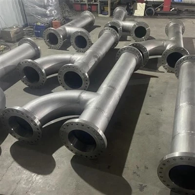
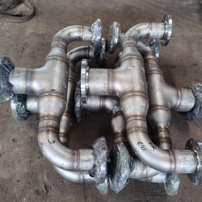
Most duplex stainless steel products leave the factory as curved shapes: pipe and tube, elbows, tees, reducers, flanges, bars, and welded spools. Their ferrite balance is checked in the field with a portable magnetic instrument, commonly called a ferritescope. Yet these instruments are calibrated on flat reference pads, and a curved surface changes how the probe couples to the steel. When the curvature, wall thickness, surface finish, or probe position are not accounted for, the displayed Ferrite Number can drift away from the true ferrite balance even though the instrument itself is correctly calibrated.

This guide settles the practical pitfalls one question at a time, in plain language. It explains why curved surfaces behave differently, which geometry thresholds matter, how to correct or qualify a reading, when the magnetic method should be replaced by a laboratory test, and what a defensible report must record. It applies to standard duplex 2205 and super duplex 2507 and 255 products supplied for oil and gas, marine, and chemical service, and it follows the procedures described in AWS A4.2M:2020 (ISO 8249:2018 MOD), ISO 8249:2018, and ISO/TR 22824:2024.
Why Does Ferrite Testing on a Curved Duplex Product Differ From a Flat Plate?
Magnetic ferrite instruments are calibrated on flat standard pads, so a curved part changes the contact area and the magnetic field path between probe and steel. The tighter the curve, the larger the possible bias; a correctly calibrated instrument can still read high or low on a small-radius pipe, a narrow-bore fitting, or a crowned weld bead.
A duplex stainless steel is roughly half ferrite and half austenite in the delivered condition. Ferrite is the magnetic phase; austenite is nearly non-magnetic. A ferritescope measures the local magnetic permeability or attractive force of the surface and converts that signal into a Ferrite Number (FN) using calibration pads whose ferrite content is already known. Those pads are flat, and the calibration assumes the probe pole faces sit evenly against a level surface.
On a convex surface such as the outside of a pipe, only the crown of the curve touches the probe; on a concave surface such as the inside of a bore, the probe poles bridge over the curve. In both cases the magnetic field partly runs through air instead of through the steel, and the instrument interprets that changed field as a change in ferrite. The same physical steel can therefore display different FN values on a flat coupon, a straight pipe section, and a tight-radius elbow. Recognizing this geometry effect is the first step toward a trustworthy curved-surface reading.
What Does an FN Reading Actually Represent on a Curved Part?
An FN reading is a standardized magnetic index, not a direct volume percentage of ferrite. On a curved surface the displayed number mixes the real ferrite content with a geometry-induced bias, so the raw value must be corrected or qualified before it is compared to a ferrite limit.
Ferrite Number is defined by ISO 8249:2018 and AWS A4.2M:2020 (ISO 8249:2018 MOD) as the magnetic measure of delta ferrite in austenitic and duplex stainless weld metal, obtained from an instrument calibrated against standard reference pads. It is a relative scale: two instruments calibrated to the same pads should agree within the repeatability expected by the standard, commonly on the order of plus or minus 10 percent of the reading after calibration.
FN is not the same as ferrite volume percent. The two scales are close in the balanced 40 to 60 percent range typical of duplex, but the relationship is not one-to-one and varies with alloy chemistry. On a curved part, two extra cautions apply:
- Raw reading is geometry-dependent. The raw FN carries the curvature, thickness, and surface bias described in this guide. A correction factor or a documented qualification may be needed before the number is compared to a specification.
- Near-surface signal. A magnetic reading reflects the near-surface layer only. It does not replace a metallographic section through the weld, HAZ, or wall when the dispute concerns through-thickness microstructure.
Specifications for duplex and super duplex commonly target 40 to 60 percent ferrite in the base material; weld metal windows are often stated in FN, and sour-service limits may fall around 35 to 65 percent. Always confirm whether the contract requires FN or volume percent before testing, because the two are not interchangeable.
How Does Convex Curvature (Pipe OD, Bar, Elbow Outside) Bias the Reading?
On convex surfaces the probe contacts only the crown of the curve. As the diameter shrinks, contact area and field coupling change, and a convex correction factor from the instrument manual should be applied. Above roughly 50 mm (2 in) diameter the convex influence is usually negligible; below that diameter, treat the raw reading with caution and correct it per the manual.
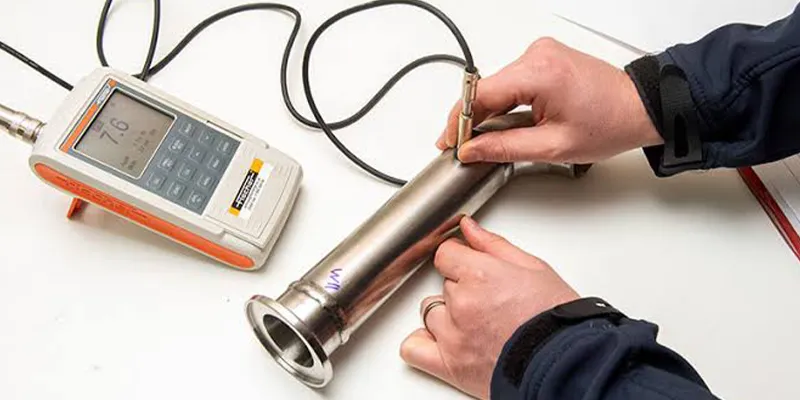
Convex curvature appears on the outside diameter of pipe and tube, on round bar, on the outside of elbows and bends, and on the crowned reinforcement of a weld bead. The probe pole faces, designed for a flat pad, rest on a narrow contact band. The magnetic field spreads sideways and partly through air, which changes the permeability signal the instrument sees.
The correction procedure used in field ferrite testing follows the instrument manual: the true ferrite content is calculated as the measured value multiplied by the convex correction factor taken from the manual chart for that diameter of curvature. The manual charts are specific to the probe and instrument model, so the factor must come from the current manual for the equipment in use, not from a generic table. As an illustration of the method, a measured 50 FN on a 20 mm cylindrical surface with a convex factor of 1.05 would be reported as about 52.5 FN after correction.
- Large radii. Large-diameter pipe and thick bar usually sit above the negligible-influence threshold; still record the outside diameter so the report can show why no correction was applied.
- Small radii. Small-bore tube, thin bar, and tight-radius elbows fall below the threshold; apply the convex chart factor, average several readings, and consider a laboratory check if the result sits near the specification limit.
The 50 mm figure is a typical threshold from instrument-manual guidance; the exact cut-off depends on the probe footprint and the ferrite range, so the current manual for the probe in service governs.
How Does Concave Curvature (Pipe ID, Fitting Inside) Bias the Reading?
Concave surfaces produce the opposite contact geometry, and the correction chart is separate from the convex one. Concave influence is usually negligible above roughly 80 mm (3 in) diameter; inside narrow-bore tubing and small fittings, the probe may not seat properly at all, and readings should be checked by a laboratory method rather than forced through.
Concave curvature appears on the inside diameter of pipe and tube, the bore of fittings and valves, and the root-side contour of a backing-groove weld. Here the probe poles bridge over the curve instead of pressing into it. The gap between pole face and steel can act like a lift-off layer, and the field path through the part is different from the flat-pad calibration.
The manual provides a separate concave correction chart that depends on the diameter of curvature; the convex factor must not be reused for a concave surface, because the two biases do not point the same way. Beyond diameter access problems, narrow bores also make good cleaning and consistent probe placement difficult, which adds scatter on top of the geometry bias.
- Wide bores. Bores larger than roughly 80 mm usually allow a standard probe to seat; still confirm the contact visually and record the inside diameter.
- Narrow bores. Bores under the threshold, or bores the probe cannot enter fully, should not be tested by guesswork. Mark the location and use a sectioned metallographic evaluation or a probe accessory specified for the geometry.
When Does Wall Thickness or Part Size Make the Reading Unreliable?
Below about 2 mm wall thickness the magnetic field runs partly in air behind the part and the reading drifts. Very small or narrow sections, roughly under 2.54 mm thick and 6.35 mm wide, are outside the reliable range of the magnetic method; those parts should be evaluated by metallographic point counting in the laboratory.

The magnetic field from the probe reaches a limited depth into the material. On a flat, thick pad the field closes through steel; on a thin wall it reaches the air behind the part, and the instrument can misread the thinner magnetic path as a lower or higher ferrite value. The same effect applies to a thin weld overlay or clad layer deposited on a different base metal: if the magnetic base metal lies within the field depth, it contributes to the signal.
Instrument-manual guidance places the thickness influence at around 2 mm (0.08 in) and below: the thinner the section, the greater the error. Field procedures and the standard practice summarized in ISO/TR 22824:2024 treat geometrically small specimens as cases where magnetic readings are not fully representative. When the wall, the clad layer, or the coupon width falls into this range, the referee route is a polished and etched cross-section evaluated by point count per ASTM E562.
How Close to an Edge, Weld Toe, or Cut End Is Too Close?
Probe placement near an edge, weld toe, or cut end distorts the magnetic field lines. Keep the probe center at the distance specified by the instrument manual; field procedures commonly use at least 50 mm (2 in) from a reference edge, and the exact measurement location must be recorded.
Field lines close through the steel around the probe. Near an edge or a sharp toe, those lines can escape into air early, changing the measured permeability. The weld toe is a special case: it is both an edge-like contour and the HAZ boundary, where ferrite balance often differs from the weld centerline. A reading taken too close to the toe may reflect the edge geometry rather than the material at that point.
- Weld locations. On a weld bead, space readings along the weld centerline and in the HAZ away from the toe radius, following the WPS or specification mapping.
- Part edges. On a cut end, flange edge, or small fitting, keep the probe clear of the part edge by the manual distance; if the geometry leaves no room, do not record an edge-adjacent reading as a representative value.
Where a required zone cannot be reached at the safe distance, document the limitation on the report instead of compensating with an informal estimate.
How Do Roughness, Heat Tint, Scale, or Contamination Affect the Reading?
Roughness moves the probe between peaks and valleys, and the bias grows as ferrite content rises. Weld heat tint, oxide scale, paint, grease, and fingerprints add a non-ferrous gap or contaminant. Clean and prepare the surface consistently, average multiple readings, and record the finish used.
A rough surface gives the probe pole faces a small but variable lift-off: one reading may sit on a peak, the next in a valley. Instrument guidance notes that this roughness effect is small below about 10 FN, but it increases as ferrite content rises, which matters directly for duplex welds typically in the balanced 30 to 70 FN region. The practical answer is to take enough individual readings at the location and average them, so peak and valley contact balance out.
Other surface conditions act as a non-ferrous layer between probe and steel:
- Heat tint. Blue, brown, or black oxide from welding without proper backing gas; porous and often chromium-depleted, it should be removed by the agreed preparation before a representative reading is taken.
- Scale and coating. Mill scale, rust, paint, coating, and weld spatter increase lift-off and must be cleaned from the measurement spot.
- Contamination. Oil, grease, and fingerprint moisture contaminate the contact; clean with solvent and handle the probe by its body, not by the pole face.
The preparation must match the condition the specification asks to evaluate. Reading an as-welded surface after grinding off the heat tint does not describe the as-welded condition, and leaving tint on some welds while cleaning others makes results non-comparable. State the finish on every report.
How Should Readings Be Distributed Across a Curved Weld or Product?
Take multiple readings at spaced locations along the weld length and around the circumference. ISO 8249:2018 calls for readings distributed along the weld axis, with several readings at each location for higher-ferrite weld metal; field practice commonly averages three to five readings per weld. Report the average and the spread, not a single lucky point.

Ferrite balance is not uniform across a weldment. The weld deposit, the HAZ, and the base metal each respond differently to the thermal cycle, and position around a pipe circumference can change cooling rate and phase balance. One reading on one spot cannot represent the joint. A defensible measurement plan covers:
- Along the weld. Several locations spaced along the longitudinal axis of the weld bead, on the finished surface.
- Zone coverage. Readings on weld metal, HAZ, and base metal where the specification calls for each zone to be checked.
- Circumference. Around the pipe or fitting circumference, with the clock position recorded, especially for manual or orbital welds.
For weld metal at or below 20 FN, a single reading per location may be sufficient under the standard; above 20 FN, several readings per location are taken and averaged. Isolated high or low readings that do not match the local trend should be treated as outliers: repeat the spot, check cleanliness and placement, and follow the outlier practice in ISO/TR 22824:2024 rather than deleting an inconvenient value silently. Report the mean, the number of readings, and the range, so the reader can judge scatter as well as average.
What Instrument and Probe Setup Matters Most on Curved Parts?
Use an instrument calibrated to AWS A4.2M:2020 or ISO 8249:2018 at the start of the shift, seat the probe vertically with consistent light pressure, lift it between readings, and keep nearby ferromagnetic tools and steel clamps away. On tight curves, check whether a small-diameter or contoured probe accessory is available for the model.
Calibration and setup account for a large share of field disagreement. The instrument and its standard pads must be matched: calibrate on the flat reference pads provided with the instrument, and re-check against a known standard every time the instrument is restarted. The flat pads remain the calibration reference; curved-surface correction, where needed, is applied after calibration.
- Probe orientation and pressure. Place the probe perpendicular to the surface, with no sideways tilt and no extra pressure that digs the poles into the curve. Keep the same hand technique on every reading.
- Lift between readings. Lift the probe off between readings instead of sliding it along the surface; sliding can scratch the finish and move the poles into a different contact condition.
- Nearby ferrous material. Low-carbon steel tools, clamps, table edges, and nearby magnetic parts distort the field. For attraction-type gauges, keep ferromagnetic objects at least about 18 mm from the probe, and follow the instrument manual for the induction type.
- Vibration. Attraction-type instruments can detach early under vibration; isolate the weldment or part from vibration during the measurement.
Some probe models offer smaller pole faces or curved-surface accessories for tube and fittings. Where such an accessory is used, record it in the report together with the instrument make, model, and calibration date, because accessory choice changes the measurement condition.
When Should You Stop Using the Ferritescope and Go to the Laboratory?
When geometry, thickness, bore size, surface condition, or an out-of-spec reading makes the magnetic result uncertain, resolve the dispute with metallographic point counting per ASTM E562 on a polished, etched cross-section. X-ray diffraction per ASTM E975 and automatic image analysis per ASTM E1245 are alternative referee methods.
The portable ferritescope is the right tool for fast production screening on accessible, adequate geometry. It has clear limits, and those limits should be respected:
- Geometry outside the reliable range. The part is thinner than about 2 mm, too narrow to seat the probe, or the bore cannot be reached.
- Borderline result. The reading sits near the specification limit and the curvature or surface bias cannot be corrected with confidence.
- Disputed qualification. The magnetic result conflicts with chemistry, hardness, or corrosion test results, or the client and supplier disagree on the FN value.
The referee methods give a volume-percent phase fraction rather than an FN index. Metallographic point count per ASTM E562 evaluates the actual microstructure on a prepared section and is the standard way to settle a weld-zone dispute; it is destructive and requires laboratory preparation. The report should state which method produced the number, so FN and percent ferrite are not compared directly without the conversion note. ISO/TR 22824:2024 also notes that diffraction-based methods can be affected by the textured weld structure, so the referee choice should follow the project specification.
How Do You Record and Report Curved-Surface Results Defensibly?
Record the instrument and calibration date, product geometry (outside diameter, inside diameter, wall thickness), measurement zone, probe orientation, surface condition, number and location of readings, any correction factor applied, average and range, and the applicable specification. A report without these fields cannot be retraced in a dispute.
Because curved-surface readings are sensitive to setup, the report must carry the context that produced them. A complete ferrite report answers the following questions:
- Equipment. Instrument make and model, probe type and accessory, calibration standard, and date of last calibration.
- Part geometry. Product description: grade and UNS number, pipe, fitting, bar, or spool; outside diameter, inside diameter, wall thickness; weld or base-metal condition.
- Location. Whether the reading is weld metal, HAZ, or base metal; clock position or zone map on the circumference; probe orientation relative to the bead.
- Surface condition. Surface finish: as-welded, cleaned, ground, or pickled; whether heat tint was removed; any contamination observed.
- Results and correction. Individual readings, mean, range, and number of readings per location; any correction factor for convex or concave curvature and its source chart.
- Criterion and limits. Specification or weld procedure referenced; acceptance limit stated in FN or percent; any limitation noted where the magnetic method could not be applied.
Permanent identity marking should be placed away from the measurement face so the mark itself does not create an artificial ferrite or edge anomaly. For spools and rotational welds, record the line number, joint number, and clock position so each reading can be tied back to the delivered product.
Table 1. Geometry and surface factors that bias a curved-surface ferrite reading
|
Factor |
Typical threshold or condition |
Possible bias |
Recommended action |
|
Convex curvature |
Influence usually negligible above about 50 mm (2 in) diameter; grows below it |
Field spreads sideways through air; signal shifts with radius |
Apply convex correction factor from the probe manual; average readings; check borderline results in the laboratory |
|
Concave curvature |
Influence usually negligible above about 80 mm (3 in) diameter; narrow bores may not seat the probe |
Pole faces bridge the curve; lift-off-like gap changes coupling |
Apply the separate concave chart factor; do not reuse the convex factor; use a laboratory section if the bore cannot be reached |
|
Wall thickness |
Influence begins below about 2 mm (0.08 in); thin cladding also affected |
Field closes partly in air behind the part; base metal may contribute |
Treat thin walls and overlays as limited-geometry cases; referee to ASTM E562 |
|
Part size |
Very small sections, roughly under 2.54 mm thick and 6.35 mm wide |
Magnetic path too small for a representative field |
Use metallographic point count instead of a portable reading |
|
Edge or toe proximity |
Keep probe center at the manual distance; field procedures commonly use at least 50 mm (2 in) |
Field lines escape early near an edge or toe |
Map safe measurement spots; record location; do not force an edge-adjacent reading |
|
Surface roughness |
Effect small below about 10 FN; increases at higher ferrite content |
Peak-versus-valley contact causes scatter |
Average multiple readings; prepare a consistent finish and document it |
|
Scale, tint, contamination |
Any non-ferrous layer or dirt on the measurement spot |
Added lift-off and uncontrolled surface condition |
Clean and remove heat tint by the agreed method; record the finish |
Table 2. Ferrite measurement methods compared for curved duplex products
|
Method |
Standard |
Reported unit |
Typical accuracy |
Best use on curved parts |
|
Magnetic induction ferritescope |
ISO 8249:2018; AWS A4.2M:2020 (ISO 8249:2018 MOD) |
Ferrite Number (FN) |
Routine field QC; model-dependent, commonly a few percent of reading |
Fast non-destructive screening on accessible, adequate-geometry surfaces; apply documented geometry corrections |
|
Magnetic attraction gauge |
AWS A4.2M / ISO 8249 family |
FN |
Comparable magnetic index; sensitive to vibration and nearby ferrous material |
Portable attraction-type checks; keep ferrous objects clear and isolate vibration |
|
Metallographic point count |
ASTM E562 |
Volume percent ferrite |
Laboratory referee method |
Dispute resolution, thin or small sections, and through-thickness HAZ evaluation on a polished etched section |
|
X-ray diffraction |
ASTM E975 |
Phase fraction |
High-precision laboratory method |
Research and high-precision QC; note that weld texture can affect diffraction results |
|
Automatic image analysis |
ASTM E1245 |
Second-phase constituent fraction |
Laboratory QC, roughly a few percent |
Quantifying etched microstructure on prepared sections where point count is unsuitable |
Table 3. Pre-measurement checklist for curved duplex ferrite testing
|
Check before testing |
Common pitfall |
Why it matters |
|
Unit and specification |
Comparing FN directly against a volume-percent limit, or vice versa |
FN and percent ferrite are related but not one-to-one; the contract must state which unit applies |
|
Calibration |
Running without checking against the standard pad after restart |
Instrument drift cannot be separated from part-to-part ferrite variation |
|
Geometry note |
Recording an FN without the OD, ID, or wall thickness |
Curvature and thickness corrections cannot be retraced or verified later |
|
Zone mapping |
Reading only the weld bead crown and missing the HAZ |
The HAZ is often the critical zone; an untested HAZ leaves the real risk uncovered |
|
Surface condition |
Mixed finishes across readings, or uncleaned heat tint and scale |
Uneven surfaces produce inconsistent attack-like scatter and non-comparable results |
|
Reading plan |
A single reading reported as the weld result |
One point cannot show the average or spread; multiple spaced readings are required |
|
Correction handling |
Applying a convex factor to a concave surface, or omitting the factor below the threshold |
The two biases differ in direction; an undocumented correction makes the report indefensible |
|
Referee fallback |
Keeping a borderline magnetic result on a thin or tiny part |
Outside the reliable magnetic range, the reading can be misleading; a laboratory section should settle it |
How Does a Fabricator Verify Ferrite on Curved Duplex Products Before Delivery?
A responsible fabricator checks ferrite balance at both levels described in this guide: portable magnetic FN screening on accessible curved surfaces, with geometry corrections and documented readings, and a metallographic section check where the geometry, a borderline result, or a dispute calls for the referee method. Jinie Technology (Jiangsu) Co., Ltd. supplies duplex and super duplex pipe, fittings, flanges, bars, and prefabricated spools for oil and gas and marine service, with in-house spectrum analysis, PMI, metallographic analysis, mechanical testing, and nondestructive inspection supporting that quality-control sequence.
The product shapes supplied are exactly the curved geometries this guide addresses: outside and inside diameters of pipe, elbows and tees, flanges, round bar, and welded spools. Each can carry the curvature, thin-wall, edge, or surface conditions that bias a magnetic reading, so the inspection plan should map the measurement zones and record the part geometry before the first reading.
The in-house quality equipment listed for production includes X-ray real-time and film inspection, a spectrum analyzer, a universal tensile tester, a metallographic analyzer, eddy-current inspection, impact testing, PMI, and hydrostatic or electrical nondestructive testing. Spectrum analysis and PMI support alloy and chemistry verification, while the metallographic analyzer can prepare and examine a polished, etched section for phase balance when the portable magnetic result is uncertain. Mechanical and nondestructive records accompany the ferrite data in the delivery documentation.
These products serve oil and gas pipelines and marine applications across Southeast Asia, the Middle East, Europe, and the Americas, where a missed ferrite imbalance can contribute to corrosion or weld rejection. The report fields listed in the previous section are what make the delivery data traceable for the client, the fabricator, and the auditor.
Key Takeaways
Portable ferritescopes are calibrated on flat pads; convex and concave curvature, thin walls, small sections, edges, rough or contaminated surfaces, and probe placement all change the displayed FN even when the instrument is correctly calibrated.
FN is a magnetic index, not a volume percent. Raw curved-surface readngs must be corrected per the instrument manual or qualified in the report before comparison to a specification limit.
Convex influence is usually negligible above roughly 50 mm diameter and concave influence above roughly 80 mm diameter; below those thresholds apply the matching manual correction chart or treat the result cautiously.
Wall thickness below about 2 mm and very small or narrow sections fall outside the reliable magnetic range; use ASTM E562 metallographic point count as the referee method.
Distribute multiple readings along the weld axis and around the circumference, cover weld metal, HAZ, and base metal as required, and report the average, range, number of readings, and any correction factor.
A defensible report records equipment and calibration, geometry, location, surface condition, results, and the governing specification. Where the magnetic method cannot be applied reliably, state the limitation and refer the question to the laboratory.