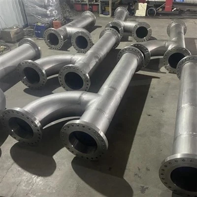
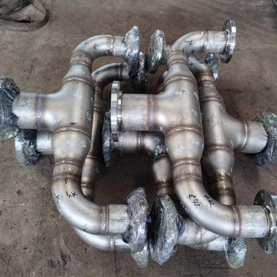
A pipe spool can look perfect in the shop and still not fit in the plant. A flange may be rotated a few millimeters, a leg may be slightly out of square, or the existing pipe it must connect to may not be where the drawing says it is. Finding that out after delivery means cutting, re-welding, and lost time. 3D laser scanning offers a different approach: capture the real geometry of the spool (and of the site) as millions of measured points, compare it with the design model, and keep the result as a permanent as-built record. This guide explains how accurate that really is, how it compares with other methods, how much time it saves, and what it means for stainless steel and nickel alloy spools.
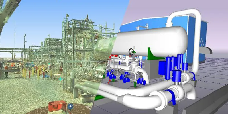
Modern terrestrial laser scanners measure points to roughly 2–6 mm accuracy depending on distance, compared with tape-measure errors that can exceed 20 mm in complex industrial settings. That is enough to verify overall geometry, fit-up, and interfaces quickly, and to create a complete as-built record. It is close to the size of common spool tolerances (about ±3 mm on lengths), so tight tolerances need careful method (fitted geometry, control points, and a more accurate instrument for critical dimensions). Scanning is strongest for complex spools, tie-ins to existing plant, and documentation; simple spools may not justify it.
What Is 3D Laser Scanning for Pipe Spool Verification?
It is a method that measures a spool (or a site) with a laser scanner, producing a dense 3D "point cloud," then compares the real geometry with the design drawing or 3D model to confirm the spool was built within tolerance.
A terrestrial laser scanner sends out a laser pulse and measures the distance to a surface by timing the round trip of the light. Rotating at high speed, it captures a full 360-degree view as a cloud of points, each with a 3D position. Scans from several positions are combined (registered) to capture all sides of the object. Software then identifies pipes, elbows, and flanges in the point cloud and compares them with the as-designed CAD model. Research groups have shown automated compliance checking of pipe spools this way, and one experiment on 30 fabricated spool assemblies benchmarked scanner-based detection of pipe and flange end points against a laser tracker.
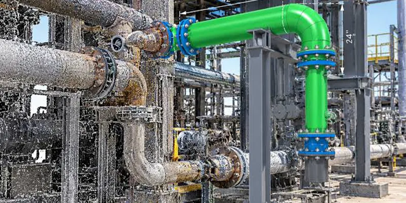
Scanning can be used in two places. In the shop, it verifies the finished spool before shipping. At the site, it records existing pipes, equipment, and obstructions, so new spools are fabricated to the real conditions rather than outdated drawings.
How Accurate Is 3D Laser Scanning for Pipe Spools?
Single-point accuracy of commercial scanners is typically about 2 mm at 10 meters, growing to about 5 mm at 40 meters, and published field studies report overall scanning accuracy of 2–6 mm depending on distance. Fitting pipe and flange geometry to many points can do better than any single point, but registration and surface effects limit the final result.
|
Scanner Specification |
Leica RTC360 (manufacturer data) |
FARO Focus Premium (reported data) |
|
3D point accuracy |
1.9 mm at 10 m; 2.9 mm at 20 m; 5.3 mm at 40 m |
About 2 mm at 10 m; 3.5 mm at 25 m |
|
Range accuracy |
1.0 mm + 10 ppm |
Ranging error about ±2 mm |
|
Range noise |
0.4 mm at 10 m; 0.5 mm at 20 m |
Not stated here |
|
Scan speed |
Up to 2 million points per second; under 2 minutes per full scan |
About 976,000 points per second |
Table 1. Published specifications of two widely used terrestrial laser scanners. Real-world project accuracy also depends on registration quality, survey control, environment, and scan overlap, as noted in independent comparisons.
Specifications describe the instrument; results depend on the whole workflow. A peer-reviewed laboratory study of the Leica RTC360 stresses that datasheet figures cannot fully describe real accuracy because hardware and software effects are hard to separate, and calls for more realistic accuracy expectations. In a large-scale project that registered many scans, reported registration errors were within about 10 millimeters for most scan pairs and slightly above that for a few. Registration error is therefore a real contributor and should be controlled with targets or survey control and checked.
Compared with the spool tolerance, the numbers are close. Common fabrication tolerances for spools are about ±1/8 inch (±3 mm) on face-to-face, center-to-face, and center-to-center dimensions, with flange rotation limited to about ±1/16 inch (±1.6 mm) and flange tilt to about 2.5 mm per meter.
A method whose point accuracy is 2–3 mm cannot by itself prove a ±3 mm dimension with large margin. A common metrology rule of thumb is that the measurement method should be several times more accurate than the tolerance it checks. This is why verification software fits cylinders and planes to thousands of points (which averages out random noise), and why critical dimensions are often confirmed with a more accurate instrument such as a laser tracker.
|
Typical Spool Tolerance |
Common Value |
Relation to Scanner Accuracy |
|
Length, face-to-face or center-to-face |
±3 mm (±1/8 in.) |
Comparable to single-point accuracy; use fitted geometry and checks |
|
Flange rotation (bolt hole offset) |
±1.6 mm (±1/16 in.) |
Tighter than single-point accuracy; verify with fitted bolt-circle geometry or a second method |
|
Flange tilt |
About 2.5 mm per meter |
Evaluate with a fitted plane across the whole face |
|
Field-fit allowance |
100–150 mm extra length on one spool |
Scanning the real gap lets the closing spool be cut accurately |
Table 2. Common pipe spool fabrication tolerances (typical industry practice; the governing project specification controls) compared with scanner accuracy.
How Does Laser Scanning Compare with Tape Measures, Laser Trackers, and Photogrammetry?
Laser scanning is far more accurate and complete than manual tape measurement, faster and more complete than a laser tracker (which is more accurate at selected points), and more accurate than photogrammetry, which is cheaper and more accessible.
In one study of scanned structures, the laser scanner had a mean square error of about 3 mm versus about 13.7 mm for a traditional tape measure, although the scanner work still took close to two hours for four structures (this was a precast concrete study, not piping, but it shows the pattern).
A 2025 review of terrestrial laser scanning for piping reports scanning accuracy of 2–6 mm versus manual measurement errors that can exceed 20 mm in complex industrial environments. Researchers working on piping fabrication quality note that photogrammetry is more economical and accessible than laser scanning but has lower accuracy, and that a laser scanner is the most appropriate tool when accuracy matters.
A laser tracker, by contrast, measures selected points with very high accuracy (a laboratory comparison reported accuracy on the order of 60 micrometers), but it does not capture the whole object the way a scanner does.
|
Method |
Typical Accuracy |
Coverage and Speed |
Best Use |
|
Tape measure and manual checks |
Errors can exceed 20 mm in complex industrial environments |
A few points per spool; slow and prone to human error |
Simple spools and quick checks |
|
Photogrammetry |
Lower than laser scanning |
Whole-object capture from photos; economical |
Documentation where tight tolerance is not required |
|
Terrestrial laser scanning |
About 2–6 mm, depending on distance |
Millions of points; whole spool or site in minutes per setup |
Complete geometry, fit-up, tie-ins, as-built records |
|
Laser tracker |
Very high; tens of micrometers in a lab comparison |
Selected points only; slower for whole objects |
Critical dimensions and calibration of scan results |
Table 3. Comparison of measurement methods for pipe spool verification. Figures come from the cited studies and manufacturer data; actual results depend on instrument, procedure, and conditions.
How Much Time and Effort Does Laser Scanning Save?
Research summarized in a 2025 peer-reviewed article reports that terrestrial laser scanning can reduce field data collection time by more than 50% compared with manual methods, while also cutting access needs such as scaffolding and lifts. Total effort depends on how much time goes into registration and data processing.
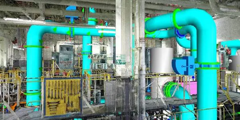
Fast capture is a major advantage: a modern scanner can complete a full-dome scan in under two minutes. Safety and access benefits are also reported in interviews with piping professionals, who cited less field exposure and reduced costs for scaffolding and personnel lifts. In a decision-support study built on a piping design case (about 72 meters of 150 mm pipe at multiple elevations with four tie-ins), a panel of 12 industry experts ranked time savings as the most important criterion (weight 0.30), ahead of dimensional accuracy (0.25), and scanning scored higher than traditional methods in that case study.
There is a counterweight. Scanning produces large data files that must be registered, cleaned, and analyzed, and the instrument and software require investment and training; many companies use third-party scanning services instead of buying equipment. The efficiency case is strongest when the alternative is repeated manual measurement, access-intensive field work, or rework.
How Does a Laser Scanning Verification Workflow Work?
The workflow has six steps: define tolerances, set up control targets, scan, register the scans, extract and compare geometry with the design model, and issue a deviation report with a pass, rework, or accept decision.
|
Step |
What Happens |
Output |
|
1. Define tolerances |
Agree the acceptance criteria from the project specification, including length, flange rotation, and tilt |
Inspection plan |
|
2. Set control |
Place targets or reference points so scans can be tied together and checked |
Control network |
|
3. Scan |
Capture the spool from multiple positions to reduce blind spots (occlusion) |
Raw scans |
|
4. Register |
Combine scans into one coordinate system and check registration error |
Registered point cloud |
|
5. Extract and compare |
Fit pipes, elbows, and flanges to the points; compare end points and orientations with the design model |
Deviation values |
|
6. Report and decide |
Issue pass/fail results with deviation maps; decide on release, rework, or field-fit allowance |
Inspection report |
Table 4. Typical laser scanning verification workflow for fabricated pipe spools.
Researchers describe similar three-stage quality models for piping fabrication, with measurement at successive fabrication stages instead of only at the end, so errors are caught while they are cheap to fix.
What Does As-Built Documentation from Laser Scanning Include?
A complete package includes the registered point cloud in an open exchange format such as E57, a deviation report against the design model, extracted centerlines and flange orientations or an updated isometric, and a record of the instrument, procedure, and accuracy used.
|
Deliverable |
Why It Matters |
Typical Format |
|
Registered point cloud |
The permanent record of actual geometry; can be re-measured later without returning to site |
E57 (common exchange format), LAS, or vendor formats |
|
Deviation report or heat map |
Shows where and by how much the spool differs from the design |
PDF with tables and images |
|
Extracted geometry (centerlines, flange orientations) |
Supports isometric updates and fit-up checks with neighboring spools |
CAD or model file |
|
Measurement record |
States scanner model, resolution, registration error, and control used, so results can be judged |
Report section |
|
Material and weld traceability link |
Ties geometry to heat numbers, weld maps, and inspection records in the quality dossier |
Document package |
Table 5. Typical as-built documentation deliverables for a scanned pipe spool or piping system.
Many scanners export point clouds to E57, which independent comparisons describe as the universal exchange format that processing software can combine and read. Keeping the raw data means a dispute or modification years later can be settled with measurements already taken. This is especially valuable for plants that lack adequate documentation, because as-built data often are not developed, saved, or kept accurate after earlier projects.
How Does Laser Scanning Reduce Rework and Fit-Up Risk?
It finds dimensional errors before shipment and records actual site conditions before fabrication, so spools fit the first time more often. Rework is a real cost: a Construction Industry Institute study reported that 13.3% of fabricated industrial pipe spools required rework.
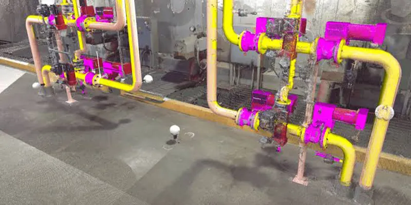
The 13.3% figure shows why verification matters. Researchers working on piping fabrication argue that traditional manual inspection is inaccurate and time-consuming and that an automated, scanner-based process reduces human error and inconsistency. They also note that a staged quality model can lower project cost by reducing fabrication rework and avoiding costly site realignments caused by defects in fabrication and delivery.
Scanning is equally useful at the other end of the pipe. In existing plants, new spools must connect to pipes and equipment whose real positions may differ from old drawings. Scanning the site before fabrication reveals the actual tie-in positions and obstructions. For the final closing joint, many projects use an extra-length spool, 100–150 mm longer than the drawing, that is cut to the measured gap in the field; scanning can measure that gap precisely and reduce guesswork.
Are There Special Considerations for Stainless Steel and Nickel Alloy Spools?
Yes. Polished or reflective surfaces can degrade scan quality, stainless steel expands more with temperature than carbon steel, and any surface preparation must not compromise cleanliness or corrosion resistance.
Reflective surfaces: Laser scanning of shiny metal is a recognized challenge. Highly polished surfaces, including 316L stainless steel, produce specular reflections, signal saturation, and spurious points, and research shows that matte coatings can improve point density and coverage on reflective metal. Most industrial spools are not mirror-polished, but bright or electropolished surfaces can be problematic. Practical responses include scanning from several angles, controlling the angle of incidence, using reference targets instead of relying on shiny surfaces, and filtering outliers.
Surface preparation and cleanliness: Matte scanning sprays can improve data on reflective parts, but stainless steel and nickel alloy spools are often cleaned and passivated to ASTM A380 and A967. Any spray, tape, or target adhesive must be approved by the project specification, be fully removable, and not leave residues that could affect corrosion resistance. Where in doubt, prefer non-contact methods such as extra scan angles and targets placed on temporary fixtures.
Thermal expansion: Austenitic stainless steels expand roughly 17 micrometers per meter per degree Celsius, compared with about 12 for carbon steel (typical handbook values). A 10-meter stainless spool measured in a shop that is 10°C warmer or colder than the reference condition would change length by about 1.7 millimeters, more than half of a ±3 mm tolerance. Record the temperature during scanning and define the reference temperature for dimensional acceptance, especially for long stainless or nickel alloy spools.
What Are the Limitations of Laser Scanning, and How Can They Be Managed?
The main limitations are accuracy close to the tolerance, registration error, blind spots, reflective surfaces, temperature effects, large data volumes, and cost and skill requirements. Each can be managed with a defined procedure and independent checks.
|
Limitation |
Why It Matters |
Management |
|
Accuracy close to tolerance |
2–6 mm accuracy is similar to a ±3 mm spool tolerance |
Use fitted geometry; confirm critical dimensions with a laser tracker or calibrated method |
|
Registration error |
Combining many scans adds error, reported at several mm and occasionally over 10 mm in one large project |
Use control targets; report registration error; check against known distances |
|
Occlusion (blind spots) |
Hidden surfaces produce no points |
Scan from additional positions |
|
Reflective surfaces |
Specular reflections create noise and missing data |
Change angles; use approved targets; filter outliers |
|
Temperature |
Stainless steel and nickel alloys expand measurably |
Record temperature; define reference temperature |
|
Cost and skill |
Equipment, software, and trained operators are needed |
Use experienced service providers or train staff; reserve for spools where the benefit justifies it |
Table 6. Limitations of laser scanning for spool verification and ways to manage them.
When Should You Specify Laser Scanning for Pipe Spools?
Specify it for complex, high-value, or alloy spools, for tie-ins to existing plant with poor drawings, for tight shutdown windows, and wherever a permanent as-built record is required. Simple, repeated spools with generous field adjustment may not need it.
|
Project Condition |
Favors Scanning |
Scanning Optional |
|
Complex geometry, many branches or offsets |
Yes |
|
|
Stainless steel or nickel alloy piping where rework is costly |
Yes |
|
|
Tie-in to existing plant with unreliable drawings |
Yes |
|
|
Short outage or shutdown window |
Yes |
|
|
Contract requires digital as-built records |
Yes |
|
|
Simple, short, repeated spools with a field-fit joint |
Yes |
|
|
Low-consequence service with generous tolerance |
Yes |
Table 7. Decision guide for specifying laser scanning verification.
When writing the specification, state the tolerance and the reference temperature, the minimum scanner accuracy and registration error allowed, the reporting format, the critical dimensions that need a second method, and the data retention period.
Frequently Asked Questions
How accurate is a 3D laser scanner for pipe spool inspection?
Commercial scanners have point accuracy around 2 mm at 10 m, rising to about 5 mm at 40 m, and field studies report 2–6 mm overall depending on distance. Fitting geometry to many points can improve feature estimates, but critical tolerances may need a second method.
Is laser scanning more accurate than a tape measure?
Yes, in complex industrial settings. Reviews report manual measurement errors that can exceed 20 mm, and one study found a scanner mean square error of about 3 mm versus about 13.7 mm for tape.
Can laser scanning verify a ±3 mm spool tolerance?
Only with careful method. Single-point accuracy is similar to the tolerance, so verification should use fitted pipes and flanges, good control, and a more accurate instrument for critical dimensions.
What format is used to store point cloud data?
E57 is a widely used open exchange format, alongside LAS and vendor-specific formats.
Does shiny stainless steel affect laser scanning?
Yes. Highly polished surfaces can cause specular reflections and spurious points. Use multiple scan angles, approved targets, and surface preparation only if it is compatible with the cleanliness requirements.
Does laser scanning reduce rework?
It can. Rework affects a meaningful share of spools (13.3% in one CII study), and scanning catches dimensional errors before shipment and records real site conditions before fabrication.