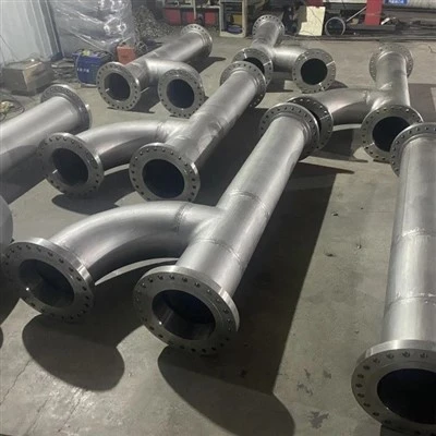
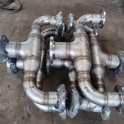
254 SMO is a 6% molybdenum super-austenitic stainless steel chosen for chloride service where 316L and even 904L struggle: seawater, desalination, bleach plants, and flue gas scrubbers. So when a 254 SMO flange shows deep attack in a ring around the gasket while the pipe wall a few centimeters away is untouched, it is both alarming and puzzling. The pattern points to the joint, not just the alloy.

A gasketed flange is a built-in crevice, and a crevice can be much more aggressive than the open surface that the alloy's pitting resistance rating describes. This guide gives a practical, evidence-based way to investigate such a failure: what to preserve, how to read the damage pattern, how to test the gasket, process, metal, and welds as causes, how to reproduce the attack in the laboratory, and how to choose the fix.
Investigate corrosion at a 254 SMO gasket in five steps: preserve the joint and its evidence, map where the attack sits on the flange face, test the likely causes (gasket material and galvanic effects, process chemistry and chlorination, weld and flange condition, assembly and geometry), reproduce or rank the cause with crevice tests such as ASTM G48 and G78, and then fix the cause rather than only the flange.
The most common culprits reported in the literature are graphite- or carbon-containing gaskets (galvanic and crevice effects), PTFE and fiber gaskets that create tight crevices, chlorinated warm chloride water, and weld or heat-tint damage near the seal. 254 SMO's high pitting resistance (PREN about 43) does not guarantee crevice resistance at a gasket.
This guide is general technical information. A failure investigation for a particular joint should be led by a qualified corrosion or materials engineer using the actual service history, samples, and laboratory results.
Why Does Corrosion Concentrate at the Seal of a 254 SMO Gasketed Joint?
Because the interface between gasket and flange is a crevice, and crevices create local chemistry that is harsher than the bulk fluid. Inside the crevice, oxygen is used up, chloride builds up, and the liquid turns acidic, so the passive film fails there first. The gasket can make this worse through galvanic coupling, leaching, or a very tight fit.
Stainless steel resists corrosion because of a thin passive film. In the narrow gap under a gasket, fresh oxygen cannot get in, so the film cannot repair itself where it is damaged. Metal dissolves, positively charged metal ions attract chloride ions into the gap, and the liquid becomes more acidic and more concentrated in chloride. That self-feeding cycle can attack metal that would be perfectly stable on an open surface.
A producer note makes the point directly: the weak point of conventional stainless steels is limited crevice resistance, and in seawater there is a considerably greater risk of crevice corrosion under gaskets, deposits, or fouling. 254 SMO raises the threshold considerably, but it does not remove the crevice.
|
Mechanism at the Seal |
How It Works |
Typical Clue |
|
Crevice corrosion |
Oxygen depletion, chloride build-up, and acidification inside the gap between gasket and flange face |
Attack under or at the edge of the gasket; sound metal outside the contact zone |
|
Galvanic corrosion |
A more noble gasket component (graphite, certain winding metals) drives corrosion of the flange face next to it |
Attack on the flange adjacent to graphite or metal windings; gasket contact marks |
|
Tight or soft gasket |
A gasket that deforms to the flange face (for example PTFE) creates a tighter, more aggressive crevice |
Uniform ring of attack matching the gasket footprint |
|
Leachable or deposited species |
Gasket or fouling releases chloride, sulfur, or other species into the crevice |
Deposits or residues in the crevice with elevated chloride or sulfur |
|
Weld or heat-tint damage |
Molybdenum segregation or oxide film near the weld lowers local resistance |
Attack at the weld toe or heat-affected zone close to the seal |
|
Process conditions |
Warm, chlorinated, stagnant, or intermittently wet service raises risk |
Damage tied to start-ups, shutdowns, or a change in chlorination or temperature |
Table 1. Mechanisms that concentrate corrosion at a gasket seal.
What Do 254 SMO's Corrosion Limits Really Mean at a Gasket?
254 SMO's pitting resistance equivalent number (about 43) and its critical pitting temperature describe open-surface pitting. At a gasket the controlling property is crevice resistance, which is lower and depends strongly on crevice geometry, gasket, and chemistry, so a flange joint should be assessed on crevice data, not pitting data.
254 SMO (UNS S31254, EN 1.4547) contains about 20% chromium, 18% nickel, 6.1% molybdenum, and 0.2% nitrogen, giving a PREN of about 43 from the standard formula (Cr + 3.3 Mo + 16 N). It falls in the NORSOK "6Mo" group (molybdenum at least 6% and PREN at least 40). A producer reports that it has been exposed to natural seawater at 60°C for prolonged periods without crevice corrosion in its tests, and a literature review ranks natural-seawater crevice resistance as 2101 duplex lower than 316L and 2304, lower than 2205, lower than 254 SMO and 2507. But the same review stresses crevice geometry, and field experience shows 6Mo and super duplex grades can suffer crevice attack at flange faces when the gasket is poorly chosen.
Two lessons follow. First, laboratory critical crevice temperature (CCT) values in ferric chloride are always lower than critical pitting temperature (CPT) values for the same alloy, and an engineering guide recommends sizing flanged joints on CCT, not CPT, because every gasket creates a crevice. Second, the severity of a real crevice depends on how tight and deep it is, what the gasket is made of, whether the joint is chlorinated or stagnant, and how it was assembled. A pass in a standard test does not guarantee a pass in your joint.
What Should You Do First When You Find Corrosion at a 254 SMO Gasket?
Preserve the evidence before cleaning or repairing anything. Photograph the joint in place, mark the orientation, retain the gasket, both flanges, the bolts, and any deposits, and record the service history. Cleaning or pickling the flange first destroys the clues.
|
# |
Action |
Why It Matters |
|
1 |
Record the joint before disassembly |
Photograph in place; note orientation (clock positions), leak path, insulation, and any staining |
|
2 |
Mark and remove carefully |
Label top, flow direction, and flange pairing; avoid scraping the crevice area |
|
3 |
Keep every part |
Retain both flange faces, the gasket (both sides), bolts, nuts, washers, and any gasket ring; bag deposits separately |
|
4 |
Collect service history |
Fluid chemistry, chloride level, chlorination or biocide, temperature range, start-ups and shutdowns, cleaning chemicals, time in service |
|
5 |
Document the build |
Gasket type and supplier, bolt torque, flange standard and face finish, welds, material certificates, installation date |
|
6 |
Sample the fluid |
Take a retained sample if the line is still in service; test chloride and any oxidizer or biocide |
|
7 |
Delay cleaning |
Clean only after photography and sampling; cleaning methods can remove corrosion products and deposits needed for analysis |
Table 2. First steps in the investigation.
Where on the Flange Face Is the Attack, and What Does That Tell You?
The location and shape of the damage narrow the cause. Attack at the inner or outer edge of the gasket, under its full width, on one flange only, at one clock position, or next to a weld each points to a different mechanism, which can then be checked.
The table below is a set of working diagnostic heuristics, based on the mechanisms in the literature. It is a starting point for the investigation, not a verdict: confirm each hypothesis with the tests in the following sections.
|
Observation |
Likely Mechanism |
How to Confirm |
|
Ring of attack matching the full gasket width, on both flanges |
Crevice corrosion from a tight gasket or aggressive chemistry |
Compare gasket type; run crevice tests with the same gasket |
|
Attack at the inner (process) edge of the gasket |
Fluid ingress and chlorinated or concentrated process liquid at the seal edge |
Review process chemistry and flow; check how far fluid penetrates |
|
Attack at the outer edge, or under insulation |
Atmospheric moisture or leakage drying and concentrating chloride |
Look for leakage history and external salt deposits |
|
Attack on one flange only |
Galvanic effect, face finish, or flange material difference |
Compare materials, face finish, and whether a graphite or metal winding contacted that face |
|
Deep attack adjacent to graphite or a metal winding |
Galvanic corrosion by a noble gasket component |
Analyze the gasket for graphite or winding metals |
|
Attack at one clock position |
Local leak path, misalignment, or uneven bolt load |
Check alignment, bolt torque pattern, and flange flatness |
|
Attack concentrated at a weld toe or heat-affected zone near the seal |
Weld microsegregation, heat tint, or intermetallic phases |
Check filler, weld procedure, and metallography |
|
Pits scattered over the flange face outside the gasket |
Open-surface pitting from chloride, deposits, or contamination |
Check chloride, temperature, and surface condition |
Table 3. Reading the damage pattern on a corroded gasketed joint.
Which Gasket Materials Increase the Risk at a 254 SMO Flange?
Graphite- or carbon-containing gaskets, PTFE and PTFE-coated gaskets, fiber gaskets, and spiral wound gaskets with 316 or Alloy 400 windings have all been associated with crevice or galvanic attack on stainless flanges. Elastomeric and aramid-type gaskets have performed better in comparative tests. Always check the specific gasket against the chemistry.
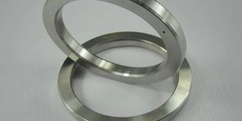
A study of gasket effects on stainless flanges in natural seawater found that natural and synthetic elastomer gaskets were less likely to promote crevice corrosion than PTFE gaskets and others containing fibers, while carbon- and graphite-containing gaskets promoted crevice corrosion.
A review of gasket selection for stainless steels in seawater explains why: graphite is electropositive (more noble) to stainless steel in chlorinated seawater and can cause galvanic corrosion on the flange face, PTFE can deform to fit the flange and create a tighter crevice, and spiral wound gaskets with 316 or Alloy 400 windings lack the crevice resistance of the flange and can release corrosion products that attack it. The review notes that graphite-containing gaskets are acceptable only if the graphite is sealed from the liquid and never wetted.
The literature includes a case that matches your situation: a review of flange failures lists UNS S31254 flange faces that corroded when used with graphite-filled spiral wound gaskets in brackish water. The reported contributing factors were the crevice between gasket and flange, the position of a weld and chlorides in the water, and galvanic currents; corrective actions included cast flanges and non-conductive gaskets.
|
Gasket Type |
Reported Behavior with High-Alloy Stainless Flanges |
Caution |
|
Graphite sheet or graphite-filled spiral wound |
Noble to stainless in chlorinated water; galvanic corrosion and crevice attack on the flange face |
Avoid in chloride service unless the graphite is fully sealed and never wetted |
|
Spiral wound with 316 or Alloy 400 windings |
Windings have lower crevice resistance and corrosion products can attack the flange |
Use windings compatible with high-alloy stainless steel |
|
PTFE and PTFE-coated |
Can conform to the face, making a tighter crevice; generally poor crevice behavior in seawater tests |
Avoid coated gaskets; test with the actual process |
|
Fiber-reinforced and synthetic fiber |
More likely to promote crevice corrosion than elastomers in the cited study |
Check the fiber and binder |
|
Elastomeric (for example neoprene) |
Less likely to promote crevice corrosion in natural seawater tests |
Check chemical and temperature compatibility |
|
Aramid-based |
Higher crevice initiation temperatures than PTFE in like-for-like tests |
Check chemical compatibility and leach-out |
Table 4. Gasket materials and reported effects on crevice corrosion of stainless steel flanges. Sources: NACE and Rolled Alloys studies on gasket selection for stainless steels in seawater, and a published review of corrosion failures of flanged gasketed joints. Results are service-specific.
How Do You Check the Gasket and the Process Chemistry as Causes?
Analyze the gasket (composition and leachables), the deposits in the crevice (chloride, sulfur, iron, other species), and the process record (chloride level, temperature, chlorination, stagnation, cleaning chemicals). Compare what you find with the conditions the alloy and gasket were selected for.
|
Check |
Method |
What You Look For |
|
Gasket composition |
Supplier data sheet; elemental analysis (for example SEM/EDS or XRF); identify filler and windings |
Graphite or carbon, noble windings, PTFE, fibers, binders |
|
Leachables |
Leaching test of a new gasket in the process liquid, followed by ion analysis |
Chloride, fluoride, sulfur, or other aggressive species |
|
Crevice deposits |
SEM/EDS and, where needed, X-ray diffraction of scraped deposits |
Chloride, sulfur, iron, calcium, biofilm remains |
|
Process chloride and temperature |
Plant records and laboratory analysis |
Levels above design; excursions; warm start-ups |
|
Chlorination and oxidizers |
Records of dosing and residuals |
Higher residual chlorine raises potential and crevice risk; review start-up in warm, chlorinated water |
|
Flow and stagnation |
Operating history |
Intermittent flow, standby periods, low-flow zones |
|
Cleaning and lay-up chemicals |
Procedures and records |
Acid, bleach, or chloride-bearing cleaners left in the joint |
Table 5. Checking gasket and process causes.
How Do You Check the Metal, Welds, and Flange Condition?
Confirm the flange really is 254 SMO in the right condition, verify the weld was made with a suitably over-alloyed filler and a controlled procedure, and check for heat tint, surface contamination, and poor face finish or flatness. Weld and heat-treatment problems can lower resistance right at the seal.
Producers describe the main metallurgical risks. 254 SMO is highly alloyed, so intermetallic phases such as sigma can precipitate at grain boundaries between about 600 and 1,000°C. Welding melts the metal and can create microscopic variations in composition, especially molybdenum, that reduce pitting resistance in the weld. For that reason producers recommend welding with an over-alloyed nickel-base filler (for example Alloy 625 or Avesta P12-type) rather than a matching composition, restricting heat input (one producer gives below 1.0 kJ/mm and interpass below 100°C), and cleaning welds, preferably by pickling. Welding without filler should be followed by solution annealing at about 1,150–1,200°C and rapid cooling.
|
Check |
Method |
What You Look For |
|
Alloy identity |
Positive material identification and certificate review |
Molybdenum near 6% and nitrogen near 0.2%; correct grade and heat treatment |
|
Condition of the metal |
Metallographic cross-section; hardness |
Intermetallic phases at grain boundaries; sensitization; cold-work or heat-affected damage |
|
Weld filler and procedure |
Weld records; positive material identification of weld metal; procedure review |
Over-alloyed filler (for example Alloy 625 type with about 9% Mo); controlled heat input and interpass; no autogenous weld without solution anneal |
|
Heat tint and cleaning |
Visual; verify pickling and passivation records |
Residual heat tint or oxide near the seal |
|
Flange face and flatness |
Measure flatness and surface finish; inspect serrations |
Damaged, rough, or uneven faces creating leak paths and deeper crevices |
|
Flange manufacturing route |
Certificate review |
Cast versus wrought flange; some reviews report castings as an option to reduce weld-related issues |
|
Assembly |
Torque records, alignment, bolt condition |
Uneven load, misalignment, galling or wrong bolt materials |
Table 6. Checking metal, weld, and assembly causes.
Note that an upgrade in weld overlay is not automatically better: one study of flanges found an Alloy 625 weld overlay performed worse than a wrought 6Mo flange in crevice testing, so overlay materials and procedures need to be qualified for the actual service.
How Do You Measure and Document the Damage?
Map every pit and crevice, measure depth and remaining thickness, examine the morphology under magnification, and section the worst area to see how the attack progressed. Clean specimens only after the photographic and deposit record is complete.
A good record includes a drawing of the flange face with the gasket footprint and every area of attack marked by clock position; photographs with a scale before and after cleaning; pit depth and density measurements following ASTM G46 (the practice for examining and evaluating pitting corrosion); measurements of remaining flange thickness and face flatness; and a metallographic cross-section through the deepest attack.
Stereo microscopy and scanning electron microscopy with elemental analysis can show whether the attack is crevice-type (concentrated under the gasket, often with a clear boundary), pitting on the open face, or associated with the weld. Cleaning of corrosion test specimens follows ASTM G1 so that the metal loss can be assessed without removing sound metal.
How Can You Reproduce or Rank the Cause in the Laboratory?
Use crevice tests to compare gasket materials, geometry, and chemistry: ASTM G48 (critical crevice temperature in ferric chloride, with controlled bolt torque) for ranking, and ASTM G78 (crevice testing guide for seawater and other chloride environments) with real gasket and flange combinations for service-like exposure. These tests rank causes; they do not predict life.
|
Test |
What It Does |
Limits |
|
ASTM G48 Method F (critical crevice temperature, stainless steels) and Method D (nickel-base and chromium-bearing alloys) |
Finds the lowest temperature at which crevice attack appears in ferric chloride, using a controlled crevice assembly and bolt torque |
Accelerated and severe; bolt torque affects crevice tightness; three to five replicates are typically needed |
|
ASTM G78 guide to crevice testing |
Describes crevice testing in seawater and other chloride waters with crevice formers such as multiple crevice assemblies |
Guide, not a pass-fail test; results depend on the water and exposure |
|
Multiple crevice assembly with the actual gasket |
Compares real gasket materials on the actual flange alloy and finish |
Needs matching metallurgy and surface finish |
|
Exposure in the actual process liquid |
Checks whether the chemistry, chlorination, and temperature drive the attack |
Longer and more expensive; control temperature and chlorination |
|
Electrochemical tests |
Measure potential and polarization of the alloy and gasket couple |
Need expertise; they support, not replace, exposure tests |
Table 7. Laboratory approaches to reproduce or rank the cause of seal corrosion. The ASTM G48 multiple crevice assembly provides many possible crevice sites per specimen, and the number of sites attacked is used as a susceptibility measure.
How Do You Decide the Corrective Action?
Match the fix to the cause. Replace the gasket if it drives galvanic or crevice attack, change the process or lay-up if chemistry is the driver, correct weld or fabrication defects, and reduce the crevice itself by design where possible. Replacing the flange with the same gasket and conditions will usually repeat the failure.
|
Root Cause |
Corrective Action |
Notes |
|
Graphite or noble gasket component |
Use a non-graphite, non-conductive gasket compatible with the process |
Literature reports success with polymeric and elastomer-type gaskets where chemically suitable |
|
Tight crevice from soft gasket (PTFE) |
Change gasket type or design a joint with less crevice |
Test the replacement in a crevice assembly before specifying it |
|
Process chemistry or chlorination |
Reduce chloride, temperature, or chlorine residual; avoid warm chlorinated start-ups; flush stagnant sections |
Document limits and monitor |
|
Weld or heat-tint damage |
Re-weld with an over-alloyed filler and controlled heat input; pickle and passivate |
Use a qualified procedure |
|
Flange face or assembly problem |
Re-machine or replace the flange; correct alignment and bolt load |
Verify flatness and finish |
|
Material limit exceeded |
Upgrade the flange or the sealing surface (for example nickel alloy), or revise the design to avoid the crevice |
Check overlay performance in tests; one study found 625 overlay inferior to a wrought 6Mo flange |
|
Design allows a deep crevice |
Redesign the joint (for example a gasket that keeps process liquid away from the flange face, or a seal-welded joint) |
One HF service case used a customized gasket to prevent direct contact of the process with the flange face |
Table 8. Matching corrective action to root cause.
Record the decision together with the evidence in a short report: service history, observations, test results, root cause, corrective action, and monitoring plan. That record is also what gives a repair credibility with operators, insurers, and regulators.
Frequently Asked Questions
Why does 254 SMO corrode at a gasket?
Because the gasket-flange interface is a crevice. Oxygen is depleted, chloride concentrates, and the liquid becomes acidic, so the passive film fails there first. The gasket material, tightness, and process chemistry can make it worse.
Is 254 SMO immune to crevice corrosion?
No. It resists crevice corrosion much better than 316L and 904L, with producer tests showing no crevice attack in natural seawater at 60°C, but field cases show attack at flange faces with poorly chosen gaskets, and crevice geometry strongly affects the result.
Which gaskets are risky on 254 SMO flanges?
Graphite or carbon-containing gaskets, PTFE and PTFE-coated gaskets, fiber gaskets, and spiral wound gaskets with 316 or Alloy 400 windings have been linked to crevice or galvanic attack. Elastomeric and aramid-type gaskets have performed better in comparative tests.
What should I do first when I find corrosion at a gasket?
Preserve the joint, photograph it, mark orientation, keep the gasket, both flanges, and bolts, record the service history, and delay cleaning until the evidence has been collected.
How do I confirm the cause?
Analyze the gasket and deposits, check process records, verify the alloy, weld, and heat treatment, and run crevice tests such as ASTM G48 and G78 using the actual gasket and flange alloy.
What filler should be used to weld 254 SMO flanges?
Producers recommend an over-alloyed nickel-base filler such as Alloy 625 type (ERNiCrMo-3) or Avesta P12-type, with controlled heat input and interpass temperature, and cleaning of welds by pickling.