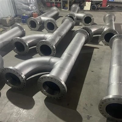
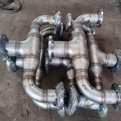
Long-length stainless steel pipe should be checked for both full-length bow and local bends using a defined reference line, controlled supports, and an agreed acceptance limit. A short straightedge can reveal a kink but cannot establish the overall shape of a long pipe. Laser measurement can map the full length, but it still depends on correct setup and interpretation.

This guide compares inspection methods rather than prescribing one universal tolerance. The workflows, sampling suggestions, and purchase-order wording below are recommended engineering practices, not additional ASTM requirements. No company test results or inspection capabilities are implied.
What does stainless steel pipe straightness actually measure?
Straightness describes departure from a specified straight reference; overall bow, local curvature, and end alignment are related but different checks.
For an endpoint-chord inspection, the reference is the straight line joining defined points at the two ends. The maximum perpendicular distance from that line describes overall bow under that particular setup. A local straightedge instead checks departure over its own contact length. Specify whether the measured feature is an outside-surface line or a reconstructed pipe centerline.
|
Check |
What it answers |
Important limitation |
|
Overall bow |
How far does the pipe deviate over its full inspected length? |
An endpoint reference and a best-fit reference can give different results. |
|
Local straightness |
Is there a bend within the specified gauge length? |
Passing local windows does not prove full-length compliance. |
|
End alignment |
Are the ends positioned and oriented for fit-up? |
End squareness, ovality, and angularity need separate definitions. |
|
Centerline straightness |
How does the reconstructed axis vary along the pipe? |
Requires a defined center-finding and fitting method. |
In simple terms, a pipe can form a gentle banana shape while appearing straight under a short ruler. It can also show little overall bow while containing a short local kink. Inspection should address the defect that matters to the installation, not just the easiest number to obtain.
Which standards determine the straightness acceptance limit?
Use the ordered product specification, its referenced general requirements, and any agreed stricter purchase-order requirements; do not apply a single internet tolerance to every stainless steel pipe.
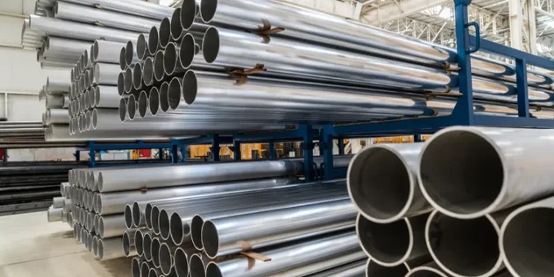
ASTM A999/A999M-23 covers general requirements for listed alloy and stainless steel pipe specifications, including A312/A312M, A358/A358M, and A790/A790M. Its scope states that the product specification prevails over conflicting general requirements, and a more stringent purchase-order requirement prevails over either.
The publicly indexed text of A999/A999M-23 distinguishes "reasonably straight" from a numerical straightedge provision for metal-arc welded pipe: a maximum deviation of 1/8 in. [3.2 mm] under a 10-ft [3.0-m] straightedge contacting the pipe at both ends. Confirm the complete clause, applicability, and ordered edition in a controlled copy before using this criterion for acceptance. It is not a blanket limit for every seamless or welded stainless steel pipe.
ASTM also requires the SI and inch-pound systems to be used independently rather than mixing rounded equivalents. State the ordered unit system. Do not turn a local straightedge limit into a full-length allowance by multiplying it by delivery length unless the governing requirement explicitly permits that calculation.
For EN-specified products or nickel alloy pipe, identify the actual product standard and edition independently. Similar alloy names, applications, or dimensions do not establish that ASTM A999 is applicable. If the contract says only "reasonably straight," agree measurable project criteria before production rather than creating a numerical rejection threshold at receiving.
How do straightedges, taut wires, lasers, and 3D systems compare?
Use a straightedge for local bends, a validated taut-line setup for economical overall screening, and laser or 3D measurement when a documented full-length profile or centerline assessment is required.
A physical or optical line provides the reference; the instrument measures departure from that reference. Laser systems can record selected stations and recalculate results against chosen reference points. Pipe-metrology guidance identifies taut lines and laser/optical lines as practical reference methods.
|
Method |
Best use |
Main error or limitation |
Recommended role |
|
Straightedge + gap gauge |
Local bends and suspicious areas |
Contact position, surface condition, gauge length; misses broad bow |
Routine local check |
|
Taut wire + offset spacers |
Low-cost overall screening |
Wire sag, wind, spacer mismatch, tension and reading technique |
Controlled screening, not an automatic precision substitute |
|
Laser + traveling target |
Long-length profile in measured planes |
Target mounting, beam stability, datum choice, sampling spacing |
Documented full-length inspection |
|
Dial indicator during rotation |
Repeatable rotational comparison on a fixture |
Runout combines bending, ovality, eccentricity and support errors |
Supplementary diagnostic only |
|
3D optical/coordinate system |
Complex axis profiles and fit-up investigations |
Surface sampling, center fitting, access and uncertainty |
Engineered inspection for tighter or disputed requirements |
This table is a selection guide, not an accuracy ranking. No generic instrument accuracy applies to every pipe length, diameter, wall thickness, surface finish, or workshop environment. A display resolution of 0.01 mm does not establish an overall measurement uncertainty of 0.01 mm. [web:39]
How should a long pipe be supported before measurement?
Agree and document the support arrangement before measuring because self-weight sag can change the apparent straightness of a long pipe.
Pipe-metrology guidance specifically recommends estimating sag and agreeing provisions for self-weight before measurements begin. Moving supports can change the measured shape without changing the pipe itself. A comparison between factory and receiving results is meaningful only when the measurement conditions are comparable.
- Unbundle the pipe and remove straps or other forces that can restrain its shape. Secure it against rolling without pulling it straight.
- Use clean, suitable cradles or rollers. Record each support location from the same pipe end, along with overhang and clock orientation.
- Keep supports stable and avoid local denting. Choose support spacing through an approved method suited to pipe stiffness and the acceptance objective.
- Allow temperature conditions to stabilize and avoid unequal sun exposure during precision inspection. Record relevant environmental conditions.
- Check more than one plane where the requirement calls for spatial straightness. A horizontal side measurement alone does not establish the vertical or three-dimensional profile.
- Do not prescribe one support spacing for every size. Thin-wall, small-diameter, and very long pipes respond differently to the same handling arrangement. If sag correction is used, document its model, assumptions, and uncertainty rather than subtracting an unexplained correction.
How is a local straightedge inspection performed?
Place a verified straightedge over the specified gauge length, establish the required contact condition, and measure the maximum gap without forcing the pipe into contact.
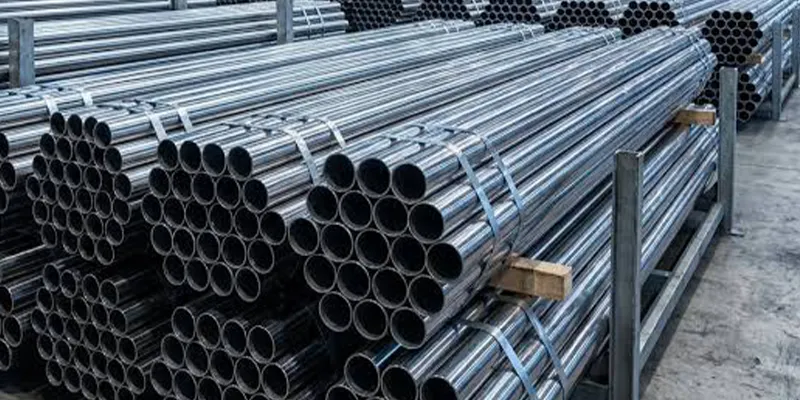
- Identify the pipe and record the gauge length, instrument identification, support layout, and inspected surface line.
- Remove loose debris. Position the straightedge with the required endpoint contact; do not bridge on a weld bead or damaged area without noting it.
- Measure the greatest gap using a suitable calibrated gap-measurement tool. Record both the value and its location.
- Move along the length with overlapping positions under the agreed procedure, paying particular attention to ends and suspect areas.
- Repeat at the required clock positions or inspect other planes using a validated setup. Compare each applicable result with the local-not full-length-limit.
Where the A999 metal-arc welded provision applies, its stated straightedge contact condition matters. A different span or contact arrangement is not automatically an equivalent test. The overlap and coverage approach above is a proposed inspection workflow, not a quoted ASTM sampling rule.
How are taut-wire and laser measurements performed over the full length?
Establish a known reference between defined end stations, measure offsets at recorded positions, and report the largest departure together with the reference convention.
For a taut wire, use defined spacers and consistent tension, then measure offsets relative to the intended reference. Wire sag and air movement can undermine results. Measuring laterally can reduce the effect of vertical wire sag on the reported horizontal offset, but it does not measure vertical pipe bow.
For a laser, align the beam with the defined reference stations and move a target along recorded positions. Easy-Laser describes recording detector positions relative to the beam and recalculating measurements using two selected reference points. The reference settings therefore belong in the inspection report.
A target traveling on the outside surface follows that surface, not automatically the pipe centerline. Ovality, local diameter changes, and target-fixture variation can enter the readings. For a centerline claim, obtain suitable cross-section measurements and apply a documented center-fitting method.
For a proposed inspection plan, start with uniformly spaced stations and add readings near ends, apparent curvature changes, and suspected damage.
Agree the spacing before acceptance. Discrete points can miss a short kink between stations, so retain the local straightedge check when local curvature matters. Use endpoint-chord, least-squares best-fit, or another defined evaluation consistently; do not switch methods to obtain a passing number.
How should bow be calculated and reported?
Report maximum deviation and inspected length separately, and add a normalized ratio only when its definition is explicit.
For an endpoint-chord check, let b be the maximum perpendicular departure and L the distance between the defined end stations. With b and L in millimeters: bow ratio (%) = 100 × b / L. A normalized value in mm/m is b / (L / 1,000). These describe the overall measurement; neither is automatically a local straightedge result.
Illustrative example-not a standard tolerance: a 12,000 mm inspected length with 9 mm maximum chord deviation has an overall bow ratio of 0.075%, or 0.75 mm/m when normalized by full length. This does not prove that every one-meter segment deviates by no more than 0.75 mm.
Where two perpendicular offsets are measured at the same station relative to a common spatial chord, their radial departure can be calculated as √(x² + y²). Do not combine the separate maximum values from different stations as if they occurred at the same location. An endpoint-chord radial result is also not automatically a minimum-zone straightness tolerance.
How can inspectors avoid false acceptance or false rejection?
Control uncertainty and agree a decision rule before judging values close to the acceptance limit.
Measurement uncertainty describes doubt associated with a reported value. It can include instrument calibration, repeatability, alignment, target seating, reference stability, temperature effects, and support-related contributions. NIST distinguishes combined standard uncertainty from expanded uncertainty, U, obtained using a stated coverage factor.
One optional buyer-agreed conservative rule is to accept only when measured deviation plus expanded uncertainty is no greater than the limit. For example, a 4.0 mm limit, 3.7 mm reading, and 0.5 mm expanded uncertainty would not meet that guarded acceptance rule because 4.2 mm exceeds the limit. That outcome does not by itself prove the pipe is physically nonconforming; it triggers the agreed review or improved measurement procedure. This example is not an ASTM-mandated decision rule.
Never treat total indicator runout as straightness without a validated separation of shape, eccentricity, and fixture effects. Similarly, repeating a reading with the same flawed datum demonstrates repeatability, not necessarily correctness.
What should the purchase order and inspection report include?
Specify the measured feature, both local and overall limits where needed, support conditions, coverage, and decision rule so that supplier and buyer evaluate the same property.
|
Contract or report field |
What to record |
|
Product definition |
Grade, product standard and edition, manufacturing route, OD, wall, ordered length and units |
|
Acceptance criteria |
Overall bow limit and reference; local gap limit and gauge length; separate end requirements if needed |
|
Measurement setup |
Surface or centerline, support coordinates, clock orientation, environmental conditions and sag treatment |
|
Coverage |
Pieces inspected, selection basis, station spacing, local coverage and any inaccessible regions |
|
Traceability |
Heat number plus individual pipe ID where piece-specific records are required |
|
Equipment and results |
Instrument IDs and calibration status, readings, maximum and location, uncertainty and decision rule |
|
Disposition |
Accepted, held for review, or rejected; inspector, date, photos and approved rework history |
For fit-up-critical long lengths, consider 100% piece inspection for the agreed checks. For less critical orders, use a buyer-approved sampling plan with an escalation rule. These are purchasing choices, not universal standard requirements. Check receiving condition after unloading; a factory report alone cannot establish that transport caused no subsequent distortion.
What should happen when a pipe fails the agreed straightness check?
Confirm the setup, hold the affected material, and obtain an approved disposition before straightening, cutting, or releasing it.
First repeat the measurement under the agreed supports and datum. Check whether the discrepancy comes from local damage, broad bow, changed support conditions, or an inconsistent evaluation method. Preserve the original readings and identify affected pieces.
Do not conceal a failed inspection by clamping a pipe straight during remeasurement. Any corrective straightening should follow an approved procedure compatible with the grade, product specification, and service requirements. Agree whether dimensional reinspection, surface examination, or additional verification is needed after rework. Shipment release should reference the final accepted condition, not a superseded report.
What are the most common questions about pipe straightness inspection?
Can a pipe pass a straightedge check but fail full-length straightness?
Yes. A short gauge can miss a broad, gentle bow. Specify and inspect both properties when both affect the intended installation.
Is laser measurement always more accurate than a taut wire?
No. A laser avoids wire sag, but reference alignment, target mounting, stability, and uncertainty still control the result. Compare validated measurement capability, not instrument labels.
Does ASTM A999 impose 3.2 mm over 3.0 m on all stainless steel pipes?
No. The indexed numerical provision is specifically identified for metal-arc welded pipe. Verify the complete ordered requirements rather than extending it to every product.
Does an MTR prove straightness compliance?
Do not assume it does. Check whether the supplied documentation actually reports the required dimensional result. Request a separate piece-linked straightness record when the purchase order requires one.
Can the same inspection approach be used for nickel alloy pipe?
The measurement principles can be adapted, but the applicable standard, acceptance limits, stiffness, supports, and handling procedure must be established for the particular product.