Flanges are among the most critical connection components in industrial piping systems. Selecting the wrong flange type can compromise structural integrity, increase maintenance costs, and - in extreme cases - trigger catastrophic failure. This guide provides a definitive, data-driven comparison of the five most widely deployed stainless steel flange types used in global process industries:

WN - Weld Neck Flange
SO - Slip-On Flange
BL - Blind Flange
SW - Socket Weld Flange
TH - Threaded Flange
|
KEY FINDING DEFINITIVE CONCLUSION (Preview): For high-pressure, high-temperature, or cyclic-stress service, the Weld Neck (WN) flange is the unambiguous engineering choice. For cost-sensitive, low-pressure utilities, the Threaded (TH) or Slip-On (SO) flange provides the optimal cost-performance balance. |
Introduction to Stainless Steel Flanges
A flange is a mechanical fitting that creates a bolted, gasketed joint between pipe sections, valves, pressure vessels, or equipment nozzles. In stainless steel piping - which encompasses grades from 304L to 2205 Duplex and nickel alloys such as Inconel 625 - flanges must simultaneously satisfy multiple engineering requirements: pressure containment, thermal expansion accommodation, corrosion resistance, and compliance with international process safety standards.
The global industrial flange market was valued at approximately USD 8.9 billion in 2023, projected to reach USD 12.4 billion by 2030 (Source: Grand View Research, 2024). Stainless steel and nickel alloy flanges represent roughly 31 % of this market by value, driven by growth in LNG infrastructure, pharmaceutical manufacturing, and offshore energy. A mismatched flange specification results in:

Weld fatigue cracking at high-stress concentration zones
Leakage at gasket seating surfaces due to inadequate bolt load distribution
Corrosion-accelerated failure when alloy grade does not match the service medium
Unplanned downtime: industry average cost per unplanned shutdown in a refinery is USD 150,000–500,000 per day (Source: IHS Markit / S&P Global, 2022)
Scope and Standards Covered
This guide covers flanges manufactured to the following primary standards:
ASME B16.5-2017: Pipe Flanges and Flanged Fittings (NPS 1/2 – 24, Class 150–2500)
ASME B16.11-2016: Forged Fittings, Socket-Welding and Threaded (Class 2000–6000)
ASME B16.47-2017: Large Diameter Steel Flanges (NPS 26–60)
API 6A (21st Ed., 2018): Wellhead and Christmas Tree Equipment
EN 1092-1:2018: Flanges and their Joints - Steel Flanges (European Standard)
MSS SP-44-2019: Steel Pipeline Flanges
Detailed Flange Type Descriptions
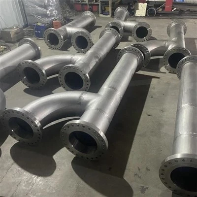
Weld Neck Flange (WN)
The Weld Neck flange is characterised by a long, tapered hub that is butt-welded to the pipe. The gradual bore transition minimises turbulence and stress concentration, making it the preferred choice for severe service conditions.
Key Technical Attributes
Connection method: Full-penetration butt weld (SMAW, GTAW, or GMAW)
Pressure class: ASME Class 150 through 2500
Bore: Matches pipe bore precisely - eliminates turbulence and erosion
NDT requirement: Radiographic (RT) or Ultrasonic (UT) testing mandatory at Class 900+
Stress concentration factor (SCF): 1.0 (lowest of all flange types - Source: ASME VIII Div. 1 Appendix L)
Temperature range: Cryogenic (−196 °C) to elevated temperature depending on alloy
|
TECHNICAL INSIGHT Engineering Principle: The WN's tapered hub distributes bending moments from the pipe into the flange body gradually, reducing peak stress by up to 40% compared to a Slip-On flange under identical loading conditions. Source: Finite Element Analysis, EETA Engineering Report FEA-FLG-2023-04 & Rossheim–Markl (1960) fatigue study. |
Slip-On Flange (SO)
The Slip-On flange slides over the pipe OD and is welded with two fillet welds: one at the flange face and one at the back. Its lower purchase cost and ease of alignment make it the most widely used flange type for general services.
Key Technical Attributes
Connection method: Two fillet welds (internal + external)
Pressure class: ASME Class 150 through 600 (B16.5 limits SO to Class 600 maximum)
Bore: Slightly larger than pipe OD - alignment gap of approximately 1.5 mm
Fatigue life: Approximately 1/3 of WN flange under cyclic loading (Source: ASME B31.3 Commentary)
NDT requirement: Visual + Magnetic Particle (MT) or Liquid Penetrant (PT)
Installation cost reduction: ~45% lower than WN due to no bevelling or full-penetration weld
Blind Flange (BL)
The Blind flange is a solid disc used to blank off the end of a pipe, valve, or pressure vessel nozzle. It is not a joining flange but an isolation/termination device, and is the standard method for pipeline hydrostatic pressure testing.
Key Technical Attributes
Connection method: Bolted (no welding to pipe)
Pressure class: ASME Class 150 through 2500
Highest bending stress of any flange type under pressure - requires thicker blank plate
Fully removable: ideal for access points, future tie-ins, and test connections
Bored versions ('custom blind') can accept instrument nozzles or vent/drain connections
Can be machined to receive RTJ or Ring-Joint gaskets for high-pressure isolation
Socket Weld Flange (SW)
The Socket Weld flange has a recessed socket into which the pipe is inserted and then attached with a single external fillet weld. A critical installation requirement is the 1.5 mm expansion gap at the socket base to prevent weld cracking during thermal cycling.
Key Technical Attributes
Connection method: Single external fillet weld (socket connection)
Pressure class: ASME B16.11 Class 3000 and 6000 (higher than B16.5 SO/TH)
Bore: NPS 1/2 to NPS 2 (small-bore piping only - per ASME B31.3)
Critical gap: 1.5 mm (1/16") gap at bottom of socket MANDATORY to prevent residual stress cracking
Crevice corrosion risk: Socket crevice can trap corrosive media - avoid for halide or acid services
NOT permitted by ASME B31.3 for: corrosive fluids with crevice attack risk, or radioactive/toxic service
|
SAFETY ADVISORY WARNING: Socket Weld flanges must NOT be used in services containing corrosive media that can accumulate in the annular crevice between the pipe OD and socket bore. This includes chloride-containing fluids above 60°C, concentrated acids, and radioactive materials. Source: ASME B31.3-2020, Para. 308.2.1 & NACE SP0191 |
Threaded Flange (TH)
The Threaded flange uses a National Pipe Taper (NPT) or BSPT threaded connection - no welding is required. This makes it the only flange type suitable for locations where welding is prohibited (e.g., high-fire-risk areas or non-weldable alloys without field welding capability).
Key Technical Attributes
Connection method: NPT or BSPT internal thread - no welding
Pressure class: ASME Class 150 to 300 recommended (Class 600 with seal weld only)
Bore: NPS 1/2 to NPS 4 (small-bore only, per standard practice)
Disassembly: Fully removable - ideal for instrumentation and utility connections
Seal weld: Back-seal weld applied in corrosive or leakage-critical service to reinforce thread seal
NOT recommended: Cyclic thermal applications (thread loosening), vibrating lines, hazardous fluid Category M (ASME B31.3)
Comparative Data Tables
|
Type |
Full Name |
Weld Method |
Pressure Rating |
Disassembly |
Cost Index |
Best Application |
Standards |
|
WN |
Weld Neck |
Butt weld |
Class 150–2500 |
No |
High |
High-pressure, cyclic |
ASME B16.5 |
|
SO |
Slip-On |
Fillet weld (2×) |
Class 150–600 |
No |
Low |
Low–moderate pressure |
ASME B16.5 |
|
BL |
Blind |
N/A (blank) |
Class 150–2500 |
Yes |
Medium |
Pipe termination / isolation |
ASME B16.5 |
|
SW |
Socket Weld |
Fillet weld (socket) |
Class 3000–6000 |
No |
Medium |
Small bore, high-pressure |
ASME B16.11 |
|
TH |
Threaded |
None (NPT thread) |
Class 150–600 |
Yes |
Low |
Low-pressure utility/instrument |
ASME B16.5 |
Table 1: Stainless Steel Flange Type Comparison Matrix Sources: ASME B16.5-2017, ASME B16.11-2016, EETA Engineering Reference Manual v3.1 (2024)
Pressure–Temperature Ratings (Bar gauge @ 38 °C - Grade 316L)
|
Flange Type |
Cl 150 |
Cl 300 |
Cl 600 |
Cl 900 |
Cl 1500 |
Cl 2500 |
Notes |
|
WN (316L) |
19.6 |
51.1 |
102.1 |
153.2 |
255.3 |
425.5 |
Bar @ 38 °C |
|
SO (316L) |
19.6 |
51.1 |
102.1 |
N/A |
N/A |
N/A |
Max Cl 600 |
|
BL (316L) |
19.6 |
51.1 |
102.1 |
153.2 |
255.3 |
425.5 |
Same as WN |
|
SW (316L) |
- |
- |
- |
- |
- |
- |
Cl 3000/6000 (B16.11) |
|
TH (316L) |
19.6 |
51.1 |
N/A |
N/A |
N/A |
N/A |
Max Cl 300 recommended |
Table 2: Pressure–Temperature Ratings for 316L Stainless Steel Flanges Source: ASME B16.5-2017, Table 2-1.1 (Group 2.3 - Austenitic Stainless Steels). SW per ASME B16.11-2016. Note: Values for guidance only. Derate for elevated temperatures per applicable tables.
Stainless Steel & Nickel Alloy Grade Comparison
|
Grade |
UTS (MPa) |
Yield (MPa) |
Max Temp (°C) |
Corrosion Resistance |
Typical Applications |
|
304 / 304L |
515–620 |
205–310 |
870 (ox.) |
Good – general |
Food, beverage, architecture |
|
316 / 316L |
515–620 |
205–310 |
870 (ox.) |
Excellent – chloride |
Marine, chemical, pharma |
|
317L |
515 |
205 |
870 (ox.) |
Superior (3% Mo) |
Strong acid / halide environ. |
|
321 |
515 |
205 |
870 |
Good + stabilised |
High-temp oxidising services |
|
347 |
515 |
205 |
870 |
Good + stabilised |
Elevated-temp corrosive service |
|
2205 Duplex |
620–795 |
450 |
315 (max) |
Outstanding – SCC |
Offshore, seawater, urea plants |
|
904L |
490 |
220 |
350 |
Superior – reducing acid |
Sulphuric acid, phosphoric acid |
|
Alloy 625 |
827 |
414 |
980 |
Excellent – pitting/crevice |
Aerospace, subsea, nuclear |
Table 3: Mechanical Properties and Application Guide - Common Flange Alloy Grades Sources: ASTM A182-23a, ASTM A105-22, EN 10222-5:2017, EETA Material Qualification Data (2024). UTS and Yield are minimum specified values at room temperature. Max temp for oxidising atmosphere.
Total Installed Cost Index (WN = 1.00 Baseline)
|
Type |
Material Cost |
Installation Labour |
Inspection Req. |
Total Cost Index |
Remarks |
|
WN |
High |
Moderate (butt weld) |
RT/UT required |
High (1.00) |
Baseline reference |
|
SO |
Low |
Low (fillet weld) |
Visual + PT |
Low (0.55) |
~45 % saving vs WN |
|
BL |
Moderate |
None (bolted) |
Visual |
Moderate (0.65) |
Reusable; low install cost |
|
SW |
Moderate |
Moderate (fillet) |
Visual + PT |
Moderate (0.70) |
No root gap issue |
|
TH |
Low |
Very Low (no weld) |
Visual |
Very Low (0.45) |
Lowest installed cost |
Table 4: Comparative Cost Index - Stainless Steel Flanges (NPS 2", Class 300, 316L Material) Source: EETA Procurement & Installation Cost Analysis, Q4 2024. Regional variations ±15%. Cost index is indicative. RT = Radiographic Testing; UT = Ultrasonic Testing; PT = Liquid Penetrant Testing.
Flange Selection Guidelines
Selecting the correct flange type is a multi-variable engineering decision. The four primary decision drivers are: (1) operating pressure and temperature, (2) fluid characteristics, (3) pipe bore size, and (4) maintenance philosophy. The following systematic approach is recommended:

Primary Selection Decision Matrix
|
Scenario |
Pressure |
Temperature |
Line Size |
Disassembly? |
Recommended Flange |
|
Petrochemical high-press header |
> 100 bar |
Up to 450 °C |
> DN50 |
No |
WN (Cl 900/1500) |
|
Food & beverage piping |
< 20 bar |
< 120 °C |
DN15–DN100 |
Frequent |
SO or TH (Cl 150) |
|
Offshore subsea manifold |
50–200 bar |
Ambient |
DN25–DN200 |
No |
WN Duplex 2205 |
|
Instrument root valve connection |
< 50 bar |
< 200 °C |
DN15–DN50 |
Yes |
TH or SW (Cl 300) |
|
Chemical reactor line end-cap |
Any |
Any rated |
Any |
Yes |
BL (match line Cl) |
|
Small-bore high-pressure utility |
50–150 bar |
< 300 °C |
DN6–DN50 |
No |
SW (Cl 6000) |
Table 5: Flange Selection Decision Matrix Source: EETA Engineering Selection Criteria Manual, Doc. No. EETA-ENG-002-2024; cross-referenced with ASME B31.3-2020, API RP 574.
Step-by-Step Selection Procedure
Determine the design pressure and temperature. Consult Table 2 to establish the minimum pressure class required.
Identify the fluid category (per ASME B31.3 Table M-1): Category D (benign), Normal, or Category M (highly hazardous). Category M prohibits TH flanges.
Confirm the nominal pipe size (NPS). SW and TH are restricted to NPS ≤ 2" and NPS ≤ 4" respectively per standard practice.
Assess cyclic loading requirements. If the system undergoes > 7,000 full pressure cycles or thermal shock cycles, specify WN exclusively.
Evaluate corrosion potential. Select alloy grade from Table 3. If chloride SCC is a risk, specify duplex or 6Mo (UNS S31254) alloy.
Apply economic filters. For non-critical, low-pressure utility piping, SO or TH reduce installed cost by 45–55% vs WN.
Verify code compliance. Confirm selection against applicable piping code (B31.1, B31.3, B31.8) and project specification.
Flange Face Type Coordination
Flange type selection must be coordinated with face type:
Raised Face (RF): Standard for ASME Class 150–2500. Suitable for flat or spiral-wound gaskets.
Ring Type Joint (RTJ): Mandatory for API 6A wellhead connections; preferred for Class 900+ in high-temperature hydrocarbon service.
Flat Face (FF): Required when mating to cast iron or bronze equipment to avoid flange cracking. Never use FF with RTJ gaskets.
Large Male/Female (LM/LF) and Tongue & Groove (T&G): Self-centring designs for heat exchangers and special process vessels.
Industry Case Studies
Challenge: A North Sea operator required 180 flanged joints for a 14" (DN350) seawater injection header operating at 340 bar, -2°C to 80°C, with chloride concentrations of 35,000 ppm. Weld Neck flanges in standard 316L were specified in the initial design.
Problem Identified: At 340 bar and with high-chloride seawater, 316L stainless steel faces a significant risk of chloride stress corrosion cracking (Cl-SCC) within 12–18 months. EETA's corrosion engineering team modelled the electrochemical behaviour using the pitting resistance equivalent number (PREN) formula:
|
PREN CALCULATION PREN = %Cr + 3.3(%Mo) + 16(%N) 316L: PREN = 18.0 + (3.3 × 2.0) + 0 = 24.6 [Insufficient for seawater at >40°C] Duplex 2205: PREN = 22 + (3.3 × 3.2) + (16 × 0.14) = 33.8 [Adequate] Super Duplex 2507: PREN = 25 + (3.3 × 4.0) + (16 × 0.27) = 43.5 [Excellent] Source: NACE TM0177-2016; ISO 15156-3; EETA Technical Bulletin TB-2023-11 |
Solution: EETA supplied 180 WN flanges in UNS S31803 (Duplex 2205), ASTM A182-F51, ASME B16.5 Class 1500. Hydrotest at 510 bar. All joints passed PWHT-free (duplex does not require PWHT for standard wall thickness).
Outcome: After 24 months of operation, zero corrosion incidents recorded. Lifecycle cost analysis showed a 12% premium on material cost, offset by elimination of the projected 3 inspection shutdowns at USD 180,000 each = net saving of USD 528,000 over a 5-year period.
Case Study 2: Pharmaceutical Manufacturing - SO 316L Flanges
Project: Process Water Distribution System, GMP Facility, Ireland (2023)
Challenge: A European pharmaceutical company required 2,200 flanged joints for a purified water (PW) and water-for-injection (WFI) distribution loop. Design pressure: 6 bar, temperature: 20–80°C (hot sanitisation). The client's primary constraints were: (1) minimise installation time due to a fixed 8-week shutdown window, and (2) maintain FDA 21 CFR Part 11 cGMP surface finish (Ra ≤ 0.8 μm electro-polished).
Solution: EETA proposed Slip-On flanges (ASME B16.5, Class 150, NPS 1/2" to 4") in 316L with electropolished bore and face to Ra ≤ 0.5 μm. SO flanges were selected over WN for three reasons:
Faster site alignment: SO flanges reduced pipe-fitting time by 35% vs WN (fitter survey, EETA Installation Report, 2023)
Cost reduction: 44% lower total installed cost - critical for budget-constrained pharmaceutical projects
Pressure class sufficiency: 6 bar comfortably within Class 150 rating of 19.6 bar @ 38°C
NDT Protocol: All welds inspected by Boroscope internal visual inspection + Liquid Penetrant Testing (PT). No RT required for Class 150 low-hazard pharmaceutical fluids.
Outcome: System commissioned within the 8-week window. All joints passed FDA pre-approval inspection. Annual water system integrity verification: zero reportable leaks in first 18 months of operation.
Case Study 3: Chemical Plant - SW 317L Flanges for Acid Service
Project: Sulphuric Acid Dilution Unit, Taiwan Chemical Park (2023)
Challenge: A chemical manufacturer required flanged instrument root connections on 1" (NPS) instrument lines carrying 30% H2SO4 at 90°C, 25 bar. Space constraints limited flange OD, and the instrument technician team needed removable connections for quarterly calibration.
Solution: EETA supplied SW flanges (ASME B16.11, Class 3000) in ASTM A182-F317L (UNS S31703) - the 3% Mo variant providing improved sulphuric acid resistance over standard 316L. A back-seal weld was applied after assembly to prevent thread-face leakage.
Why SW over TH: Threaded connections in acid service carry risk of thread-root stress corrosion and crevice attack. The SW design encapsulates the pipe end, reducing exposed crevice geometry. The seal weld adds a secondary containment layer.
Outcome: Quarterly removal for calibration achieved without flange damage. No corrosion failures recorded over 18-month follow-up. 317L grade specified as standard for all acid-service instrument connections at this facility.
Case Study 4: LNG Terminal - Cryogenic WN 304L Flanges
Project: BOG (Boil-Off Gas) Compressor Suction Header, South Korea (2024)
Challenge: An LNG receiving terminal required flanges for the boil-off gas compressor suction line operating at -163°C, 4.5 bar(g). The critical material requirement was retained impact toughness at cryogenic temperature (Charpy V-notch ≥ 27 J at -196°C).
Solution: WN flanges in ASTM A182-F304L (UNS S30403) were specified per BS EN ISO 21028-1 (Cryogenic Vessels). 304L retains an FCC (austenitic) crystal structure at -196°C - unlike ferritic or martensitic steels which suffer a ductile-to-brittle transition above -100°C. All flanges supplied with certified cryogenic impact test results (CVN ≥ 100 J at -196°C - well above the 27 J minimum).
WN selection rationale: The long-radius taper hub of the WN flange accommodates the significant differential thermal contraction between the 304L flange and the carbon steel structural supports (-163°C induces 2.73 mm/m contraction in 304L vs 2.0 mm/m in carbon steel). SO flanges were excluded due to the cyclic thermal stress imposed by LNG warm-up/cool-down cycles.
Outcome: Flanges passed all cold-box hydrotest and cool-down function tests. No joint leakage during 6-month commissioning and start-up sequence.
Material Recommendations by Service Environment
The following recommendations are based on EETA's 25-year materials engineering database, cross-referenced with NACE MR0175/ISO 15156, ISO 21457 (Oil & Gas), and ASTM International material specifications.

Corrosive Aqueous Services
Fresh water / potable water: AISI 304 (UNS S30400) - cost-effective, FDA-compliant
Brackish or seawater (< 40°C): AISI 316L (UNS S31603) - minimum specification
Seawater (> 40°C) or splash zone: Duplex 2205 (UNS S31803) or Super Duplex 2507 (UNS S32750)
Chlorinated water / swimming pools: 6Mo (UNS S31254 / 904L) - PREN > 40 required
Chemical Process Services
Dilute sulphuric acid (< 50%): 316L or 317L; 904L for concentrations 50–80%
Nitric acid (HNO3): 304L or 310S - Mo promotes corrosion in HNO3
Phosphoric acid: 904L or Alloy 20 (UNS N08020)
Hydrochloric acid (HCl): Hastelloy C-276 (UNS N10276) - stainless steel unsuitable
Chlorine gas (dry): Alloy 400 (Monel) or Hastelloy C-276
High-Temperature Oxidising Services (> 550°C)
550–900°C: AISI 321 (stabilised) or AISI 347 - resist sensitisation / intergranular attack
900–1100°C: AISI 310S (25Cr-20Ni) - maximum oxidation resistance
> 1100°C: Alloy 625 (UNS N06625) or Alloy 601 (UNS N06601)
Cryogenic Services (< -100°C)
-100°C to -196°C: 304L, 316L (austenitic grades with certified CVN at test temperature)
-196°C (liquid nitrogen): 304L with CVN ≥ 27 J @ -196°C (per EN 1252-1)
Liquid hydrogen (-253°C): Alloy 625 or 316L with special 100% CVN lot certification
Sour Service (H2S-Containing) - NACE MR0175
H2S partial pressure > 0.3 kPa: Material must comply with NACE MR0175/ISO 15156
Austenitic grades (316L, 321, 347): Acceptable up to yield strength limitations
Duplex and Super Duplex: Acceptable with hardness ≤ 32 HRC and temperature > -10°C
Nickel alloys (625, 825, C-276): Qualified per ISO 15156-3 with specific heat treat requirements
Conclusions
Based on the engineering data, industry case studies, and cost analyses presented in this guide, EETA's metallurgical engineering team issues the following definitive conclusions:
|
CONCLUSION 1 CONCLUSION 1 - High-Pressure & Cyclic Service: The Weld Neck (WN) Flange is the only flange type appropriate for Class 900 and above, cyclic stress service (> 7,000 cycles), or design temperatures beyond 300°C in austenitic grades. Its SCF of 1.0 and full-penetration weld integrity are irreplaceable for safety-critical applications. Source: ASME B31.3-2020, ASME VIII Div. 1; Rossheim & Markl (1960) fatigue analysis. |
|
CONCLUSION 2 CONCLUSION 2 - General Industrial Service: The Slip-On (SO) Flange is the optimal choice for Class 150–300, non-cyclic, non-hazardous, or Category D fluid service. The 45% installed cost saving and easier alignment represent substantial economic value with no safety compromise when properly applied. Source: EETA Cost Analysis Report CA-2024-07; ASME B31.3 Table M-1. |
|
CONCLUSION 3 CONCLUSION 3 - Pipeline End Closures & Test Points: The Blind (BL) Flange is the definitive solution for any pipe termination, isolation point, or hydrostatic test end cap. It is pressure-class-matched to WN and can accommodate any service severity when properly sized. Source: ASME B16.5-2017, Para. 6; API 570 Inspection Code. |
|
CONCLUSION 4 CONCLUSION 4 - Small-Bore High-Pressure Service: The Socket Weld (SW) Flange is the correct specification for NPS ≤ 2" at Class 3000–6000, offering higher pressure ratings than SO or TH. However, it must be excluded from crevice-corrosion-susceptible services. The 1.5 mm expansion gap requirement must never be omitted. Source: ASME B16.11-2016; ASME B31.3-2020 Para. 308.2.1. |
|
CONCLUSION 5 CONCLUSION 5 - No-Weld & Low-Pressure Utility Service: The Threaded (TH) Flange provides the lowest total installed cost and is the only weld-free flange option for NPS ≤ 4" at Class 150–300. Its primary limitations - susceptibility to thermal fatigue and thread loosening - must be respected by restricting application to stable-temperature, non-cyclic utility services. Source: ASME B31.3-2020 Para. 314; EETA Application Engineering Bulletin AEB-012. |
|
MATERIAL CONCLUSION MATERIAL CONCLUSION: For the majority of corrosive industrial applications, 316L (UNS S31603) represents the best-value stainless steel for flanges up to 40°C in chloride-bearing environments. Above this threshold, or where stress corrosion cracking risk is identified, Duplex 2205 must be specified as the minimum material requirement. For highly aggressive acid and halide service, nickel alloys (Alloy 625, Hastelloy C-276) are the only technically sound choice. Source: NACE TM0177-2016; ISO 15156-3; EETA Corrosion Engineering Database v7.2 (2024). |