


Fully austenitic stainless steel welds crack during solidification because, without a small amount of delta ferrite present, low-melting sulfur and phosphorus impurities segregate into thin liquid films along solidifying grain boundaries and tear apart under cooling stress. The standard industry control is to target a Ferrite Number (FN) of roughly 3 to 10 using the WRC-1992 diagram - enough ferrite to trap those impurities, but not so much that it degrades corrosion resistance or promotes brittle sigma phase in service.
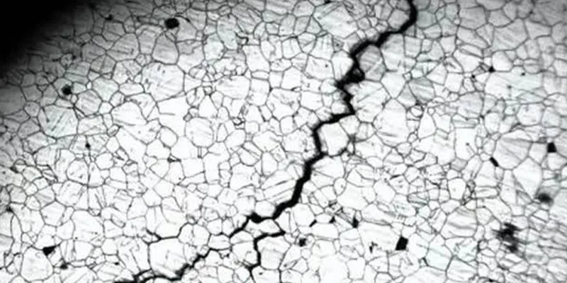
Austenitic stainless steel welds - 304, 316, and their many variants - are among the most commonly welded materials in industry, and most of them tolerate welding well. But a specific subset of applications, from cryogenic vessels to fully austenitic grades like 310 and 330, remove the very feature that normally protects these welds from cracking: delta ferrite. This article explains the mechanism behind solidification cracking, why Ferrite Number is the primary lever for controlling it, and what to do when the application genuinely can't tolerate the ferrite that would otherwise solve the problem.
Why Do Austenitic Stainless Steel Welds Crack During Solidification?
Solidification cracking happens when residual sulfur and phosphorus impurities segregate into thin, low-melting liquid films along the boundaries of solidifying grains, and cooling stress tears those still-weak boundaries apart before they can fully solidify.
As weld metal cools from liquid to solid, it doesn't solidify all at once - grains form and grow, and residual impurities that don't fit into the crystal structure get pushed ahead of the advancing solid front. Sulfur and phosphorus are the primary offenders: both combine with matrix elements to form compounds with melting points lower than the surrounding metal, and both readily segregate to the last-to-solidify regions at grain boundaries.
As the weld continues cooling and contracting, it generates tensile stress across those boundaries. If a thin liquid film of these low-melting impurities is still present when that stress arrives, the boundary has essentially no strength to resist it, and it tears - producing a solidification crack, sometimes visible on the surface, sometimes buried within the weld.
What Is Ferrite Number, and Why Does a Small Amount of Ferrite Prevent Cracking?
Ferrite Number (FN) is a standardized, magnetically measured index of how much delta ferrite is present in austenitic weld metal, and that ferrite matters because it dissolves sulfur and phosphorus far more readily than austenite does, keeping those impurities from concentrating into crack-causing liquid films.
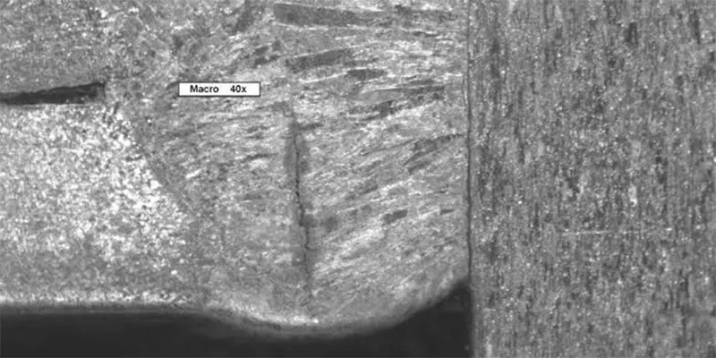
Delta ferrite is beneficial in dissolving phosphorus and sulfur, low-melting impurities that would otherwise segregate out during solidification and lead to cracking during subsequent weld passes. Ferrite has a higher solubility limit for these elements than austenite does, so when a weld solidifies with even a modest amount of ferrite present, that ferrite acts as a sink - absorbing sulfur and phosphorus into solid solution instead of letting them concentrate into thin liquid films at grain boundaries.
Ferrite is also believed to act as a physical binder between solidifying austenitic dendrite columns; with too little ferrite present, those parallel dendrite columns can split open along their length as a crack. Because FN is measured with standardized magnetic instruments and reported on an internationally recognized scale, it gives welding engineers a practical, repeatable number to target - rather than relying on a purely qualitative sense of 'enough' ferrite.
What Ferrite Number Range Should Welders Target?
Industry practice generally targets an FN in the range of roughly 3 to 10 for standard austenitic grades like 308, 308L, 309, and 316 - enough to reliably resist solidification cracking without introducing the corrosion or embrittlement problems that come with excess ferrite.
This range isn't arbitrary: it represents the balance point between two competing risks. Below roughly 3 FN, there generally isn't enough ferrite reliably present, at a consistent and predictable level across the weld, to guarantee crack resistance - variation in cooling rate, dilution, or minor chemistry shifts can push isolated regions of the weld toward zero ferrite even when the target on paper looked adequate.
Above roughly 10 FN, other problems start to emerge, covered in more detail further below. For fully austenitic base metals with unusually low sulfur and phosphorus content, and matching low-impurity filler metal, welding can sometimes be done successfully outside this range - but that requires deliberately engineered chemistry, not standard practice.
How Do the Schaeffler, DeLong, and WRC-1992 Diagrams Predict Ferrite Content?
These constitution diagrams plot a weld's chromium equivalent against its nickel equivalent to predict both the resulting ferrite content and the solidification mode, with the WRC-1992 diagram now regarded as the most accurate and widely adopted version.

All three diagrams work on the same underlying principle: certain alloying elements behave like chromium in promoting ferrite (chromium itself, molybdenum, niobium, silicon), while others behave like nickel in promoting austenite (nickel, carbon, nitrogen, manganese, copper). By combining a weld metal's actual composition into a chromium-equivalent (Creq) and nickel-equivalent (Nieq) value, and plotting the ratio, these diagrams predict both the resulting delta ferrite content and - critically - the mode in which the weld solidifies.
The WRC-1992 diagram improved on its predecessors by adding a coefficient for copper in the nickel-equivalent calculation, correcting a tendency of the earlier WRC-1988 diagram to overestimate FN in copper-containing weld metals, and validation against more than 200 independent weld metals confirmed its superior predictive accuracy over the older Schaeffler and DeLong diagrams.
|
Diagram |
Key Characteristic |
Best Use Case |
|
Schaeffler (1949) |
Original constitution diagram; simpler equivalency formulas |
Historical reference; general estimation |
|
DeLong (1956) |
Refined for austenitic weld metals; incorporates nitrogen |
Improved accuracy for common 300-series grades |
|
WRC-1992 |
Most accurate; corrects copper overestimation; widely adopted, including by ASME |
Current industry standard for FN prediction |
Why Does Solidification Mode Matter More Than Ferrite Content Alone?
A weld that solidifies as primary ferrite (the FA mode) is inherently far more resistant to cracking than one that solidifies as primary austenite (the AF mode), even at a similar final ferrite content - because the sequence in which the phases form determines how effectively impurities get swept into the ferrite rather than trapped in the last liquid to solidify.
Most austenitic stainless steel welds are designed to solidify in the ferritic-austenitic (FA) mode: primary delta ferrite forms first, with austenite forming afterward through a solid-state or eutectic-type transformation. This sequence is what allows ferrite to effectively scavenge sulfur and phosphorus during solidification. The alternative, austenitic-ferritic (AF) or fully austenitic (A) solidification, offers far less protection, because impurities have no ferrite phase available early in solidification to be absorbed into.
The transition between these modes is governed by the Creq/Nieq ratio: a ratio below roughly 1.5 tends toward primary austenite solidification, while ratios above that threshold shift toward primary ferrite, with different studies placing the precise transition point for common welding processes ranging from about 1.5 to as high as 1.9–2.0 depending on the specific equivalency formula used.
This is why two welds with a similar final measured FN can have very different real-world cracking resistance - the diagrams predict solidification mode specifically because mode, not just final ferrite quantity, governs how well impurities get controlled during the vulnerable window of solidification.
What Happens When the Application Truly Requires Zero or Near-Zero Ferrite?
Certain services - cryogenic vessels needing maximum low-temperature toughness, and fully austenitic grades like 310, 320, and 330 that can't reliably form ferrite at all - remove the ferrite safety margin entirely, which is why these welds are recognized as significantly more crack-sensitive and require tighter process control than standard 308/316 welding.

For cryogenic-temperature service, low-temperature impact strength decreases as ferrite content increases, creating a direct conflict: the ferrite that resists cracking also reduces the toughness the application needs at low temperature, so these welds require a closely balanced FN to achieve adequate crack resistance alongside good low-temperature impact strength, rather than simply maximizing ferrite.
Fully austenitic filler grades - 310, 320, and 330 - present an even more difficult case: their compositions are inherently more crack-sensitive than their ferrite-fortified relatives, and all phases of welding and inspection require greater attention as a result. For these grades, the accepted practice is to compensate through filler metal chemistry and process discipline rather than through ferrite content: using filler metal with low sulfur and phosphorus and increased manganese content, since manganese helps bind sulfur and reduce its embrittling effect even without ferrite present to do the same job.
Do Sulfur and Phosphorus Matter Even When Ferrite Number Looks Acceptable?
Yes - a direct, documented relationship exists between the combined phosphorus-plus-sulfur content and crack sensitivity, independent of ferrite level, meaning a weld with technically sufficient FN can still crack if impurity content is high enough.
Research specifically examining autogenous welding of Type 309 stainless steel identified a clear relationship between the sum of phosphorus and sulfur content, the ferrite level in the weld metal, and the resulting crack sensitivity. The practical implication is that ferrite control and impurity control are two separate levers that both need to be pulled, not one substituting for the other: strict limitations on carbon, phosphorus, and sulfur in both the base material and welding consumables remain essential even in welds with adequate FN, and the two most crack-sensitive grades in common use - 310 and 330 - are exactly the ones where impurity control has to compensate for the ferrite margin that isn't reliably available.
Does Too Much Ferrite Cause Its Own Problems?
Yes - above roughly 10 FN, excess ferrite raises the risk of embrittling sigma phase formation in elevated-temperature service, and in molybdenum-bearing grades like 316, higher ferrite content can meaningfully reduce corrosion resistance in hot oxidizing environments.
Sigma phase risk: above about 10 FN, there is danger of ferrite - which holds chromium in solid solution - transforming into brittle sigma phase when service temperature falls in the roughly 1000–1650°F (540–900°C) range, and in some multipass welds, the heat of welding alone can produce sigma phase in high-ferrite welds without any separate elevated-temperature service exposure.
Corrosion resistance in Mo-bearing grades: in molybdenum-bearing grades such as 316 and 317, higher ferrite content can cause a major decrease in corrosion resistance in hot oxidizing media, such as urea service - a specific, well-documented exception to the general rule that more ferrite is safer.
Reduced low-temperature toughness: as already noted for cryogenic applications, impact strength at low temperature declines as ferrite content rises, working directly against crack resistance in that specific service condition.
This is why FN control is presented as a target range rather than a 'more is better' maximization strategy - the correct number depends on the specific grade, the service temperature, and the corrosion environment, not a single universal ceiling or floor.
What Welding Practice Changes Reduce Cracking Risk in Low-Ferrite Grades?
For crack-sensitive, low-ferrite grades, minimize restraint, keep heat input and interpass temperature low, favor slower cooling through the vulnerable solidification range, and deliberately avoid smooth, well-washed weld bead profiles in favor of more convex, crowned beads.

Minimize mechanical restraint in the joint design and fixturing, since cracking is fundamentally driven by stress acting on a still-weak, partially solidified boundary.
Keep heat input low and control interpass temperature - guidance for the most crack-sensitive grades specifically recommends keeping interpass temperature below roughly 210°F (99°C).
Control weld bead profile deliberately: smooth, flat, well-washed beads crack more readily in the most crack-sensitive grades, while more convex, crowned bead profiles are more crack-resistant, a counterintuitive but well-documented practical guideline.
Control silicon content in the weld metal, particularly in submerged arc welding, since high-silicon weld metal is more crack-susceptible than low-silicon weld metal, and silicon pickup from welding flux should be accounted for.
Select filler metal chemistry deliberately for fully austenitic grades - low sulfur and phosphorus, elevated manganese - rather than relying on base-metal ferrite that these grades cannot reliably provide.
How Should Ferrite Number Be Verified During and After Welding?
FN should be verified with a calibrated magnetic ferrite measurement instrument on production welds or representative test coupons, cross-checked against the constitution diagram prediction used at the welding procedure qualification stage, since actual measured FN and diagram-predicted FN can diverge with dilution and process variables.
Magnetic ferrite measurement instruments provide a practical, non-destructive way to verify actual FN on completed welds, and this measured value is what should ultimately govern acceptance - not just the calculated prediction from a constitution diagram. It's also worth noting that FN as measured does not always equal the true volume percent of ferrite present: at roughly 8–10 FN and below, the FN approximately equals the average volume percent of delta ferrite in a weld, but at higher FN values, the measurement can increasingly overestimate actual ferrite content, which is one more reason the 3–10 FN target range aligns well with the range where FN measurement itself remains most reliable and physically meaningful.
Frequently Asked Questions
What Ferrite Number is generally recommended to prevent solidification cracking?
Roughly 3 to 10 FN for standard austenitic grades such as 308, 308L, 309, and 316, calculated using the WRC-1992 diagram and verified on the actual weld with a calibrated magnetic ferrite instrument.
Why are fully austenitic grades like 310 and 330 harder to weld crack-free?
Their compositions don't reliably form the delta ferrite that protects most austenitic welds from cracking, so crack resistance has to come instead from tightly controlled filler metal chemistry - low sulfur and phosphorus, increased manganese - and disciplined welding procedure rather than ferrite content.
Can a weld crack even if its Ferrite Number is within the recommended range?
Yes, if sulfur and phosphorus content is high enough. Ferrite control and impurity control are separate factors that both need to be managed; adequate FN reduces but does not eliminate the crack risk from excessive residual impurities.
Is more ferrite always safer for austenitic stainless steel welds?
No. Above roughly 10 FN, welds become more susceptible to embrittling sigma phase in elevated-temperature service, and in molybdenum-bearing grades, higher ferrite can reduce corrosion resistance in hot oxidizing environments, so FN is managed as a target range, not maximized.
Which constitution diagram is considered most accurate for predicting Ferrite Number?
The WRC-1992 diagram is generally regarded as the most accurate diagram currently available, validated against more than 200 independent weld metals and adopted as a reference in codes including the ASME Boiler Code.







