|
What controls a spool |
The 3D model, not the isometric. Isometrics, weld maps, cut lists and bills of material are all derived from it, so a model change propagates to every shop document automatically. |
|
Spool versus piping isometric |
The piping isometric shows the whole line. The spool drawing (fabrication isometric) shows one transportable assembly with cut lengths, weld numbers, fit-up dimensions and a spool number. |
|
Shop versus field welding |
Shop welds run 98% first-pass radiographic acceptance against 90-93% in the field, with rework of 1-2% against 7-10%, and shop labour at 50-80 USD/hour against 120-200 USD/hour in the field. |
|
Alignment at the joint |
ASME B31.3 limits internal misalignment to 1.6 mm for NPS 24 and smaller, and 3.2 mm for NPS 26 and larger where the welding procedure allows it. |
|
Root protection |
Back-purge with argon to 50 ppm oxygen or lower for nickel alloys, 25-50 ppm for duplex, and 50-100 ppm for standard austenitic stainless. Nitrogen is prohibited for back-purging stainless and duplex because it is absorbed into the weld pool. |
|
NDE acceptance |
ASME B31.3 para. 344.6.2 rejects a linear ultrasonic indication when its amplitude exceeds the reference level and its length exceeds 6 mm for wall thickness up to 19 mm, or one third of the wall thickness above 19 mm. |
|
Shop versus field position |
A shop can rotate a spool into the flat position for welding. The same joint in the field is usually vertical (6G), which is slower, harder to inspect and far more likely to be repaired. |
|
Spool size in practice |
Transport and handling set the practical limits - about 12 m maximum length and 5-10 tonnes maximum weight are the numbers most fabricators design to. |
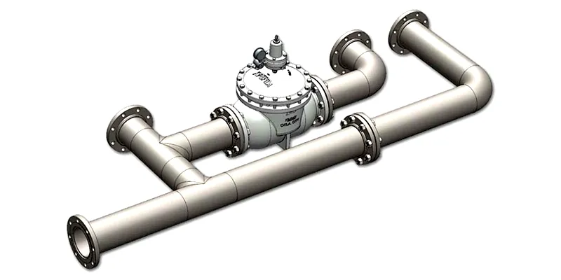
A pipe spool only becomes a good spool if the information that defines it survives the trip from the 3D model to the welder. The model holds the geometry, the isometric turns that geometry into a cut list, the weld map turns the cut list into qualified joints, and the shop workflow turns the joints into an inspected, tested, traceable assembly. Break any link in that chain and the cost shows up later as a mis-cut length, a rejected weld or a package the inspector will not release. This guide walks the whole chain, from how a model is broken into spools, through beveling, fit-up, purging and welding, to NDE, testing and the document package that travels with the steel.
Most fabricators can weld. Far fewer can show you, document by document, exactly where a given cut length, a given weld number and a given mill certificate came from. That gap is not a welding problem. It is an information problem, and it is exactly what a 3D model resolves when it is used as the parent document rather than as a visual aid. For the background on what a spool is and how the broader prefabrication business is structured, read the site guide on what pipe spool fabrication is and how it works. For the money side, the shop-versus-field arithmetic is broken out separately in the cost comparison between shop and field welding.
Why does a 3D model have to come before the isometric in pipe spool fabrication?
Because the isometric is a projection of the model, and a projection that is redrawn by hand is no longer a projection. When a spool drawing is produced by extracting geometry from a controlled model, every cut length, every elbow angle and every weld location is guaranteed to agree with every other document in the set. When the same drawing is drafted manually, agreement depends on the drafter's care on the day, and it silently fails at the first revision.
This matters more in modern plants than it did a decade ago, for a simple reason: the density of branch connections. A line that leaves a pump in a chemical plant may carry twenty nozzles in a few metres, each one a potential mismatch between a model, a take-off, a cut list and a spool. The rationale is a control argument, not a productivity one. A model-based workflow replaces the coordination of many people with the consistency of one database, so the quality of the finished spool stops depending on how carefully the drawing was checked by eye.
There is a second reason that matters commercially. When the model, the isometric, the weld map and the bill of material are all generated from one revision, a design change is a model change, and the shop learns about it automatically. When they are separate documents, a design change becomes a reconciliation exercise across four files, and the reconciliation is where the cost hides.
The model-to-shop data chain and what each output drives
|
Model element |
Derived shop document |
What it controls in the shop |
If it is wrong |
|
Component geometry and routing |
Piping isometric |
Route, bend angles, overall dimensions |
Weld is cut to the wrong length and will not fit the run |
|
Component position and orientation |
Spool drawing dimensions |
Fit-up dimensions, flange clocking, branch elevation |
Branch lands in the wrong place at site |
|
Component schedule and grade |
Bill of material |
What pipe, fittings and flanges are issued to the shop |
Wrong alloy is welded into a sour line |
|
Joint topology |
Weld map |
Which welds exist, their WPS, NDE and welder |
A joint is welded with no qualified procedure and cannot be signed off |
|
Spool partitioning |
Spool list and weight |
Handling, transport and crane planning, and the field weld count |
Spool is too heavy to lift or too long to ship |
|
Test boundaries |
Test package and spool orientation marks |
Which spools are hydrotested together and how they are marked |
Wrong boundary is tested and the line is not |
Key point: The single most valuable control in a spool shop is the rule that the isometric, the weld map, the cut list and the bill of material are all printed from the same model revision on the same day. Mixed-revision document sets are the most common cause of a spool that passes fabrication and fails inspection.
What is the difference between a pipe spool, a piping isometric and a spool drawing?
They are three different things, and confusing them causes real cost. A piping isometric is the engineering view of a whole line. A spool drawing, also called a fabrication isometric or spool piece drawing, is the shop document for one transportable assembly. The spool is the physical object produced from that drawing.
The distinction matters because the two drawings answer different questions and are checked by different people. The piping isometric is verified against the piping class, the P&ID and the stress analysis, mostly by engineers. The spool drawing is verified against the piping isometric, the cut list and the transport limits, mostly by the fabrication shop. Neither replaces the other, and a spool fabricated from a piping isometric instead of a spool drawing is a job with no cut lengths on it.
The reasoning behind the split is reliability. A piping isometric is a summary of a route and is correct at the level of the design. A spool drawing is a cutting and assembly instruction, and it has to be correct at the level of the millimetre. Deriving the second from the first, in software, is what removes the transcription step where errors are introduced.
Design isometric against fabrication isometric
|
Attribute |
Piping isometric (design) |
Spool drawing (fabrication) |
|
Scope |
The complete line from one terminal point to the next |
One transportable assembly, typically one to six components |
|
Primary use |
Design review, stress analysis, material take-off, construction planning |
Cutting, fitting, welding, inspection and site installation |
|
Dimensioning |
Route coordinates, elevations, overall run length |
Cut lengths, center-to-end, center-to-face, fit-up and field weld take-up |
|
Identification |
Line number and isometric number |
Spool number, line number, weld numbers, orientation mark |
|
Material callout |
By piping class, on the component |
Per item, with grade, size, schedule, quantity and heat traceability required |
|
Weld information |
Joint locations and type |
Weld number, joint type, WPS reference, NDE method and extent |
|
Test information |
Test boundary and design pressure |
Whether this spool is included in a test and what the hold points are |
|
Issued by |
Design engineering |
Fabrication engineering, from the design isometric |
|
Status for the shop |
Reference only |
Controlling document for fabrication |
If you want the wider vocabulary explained, how pipe fittings are specified and dimensioned covers the components that end up inside these drawings, and buttwelding fittings covers the joint types that drive the welding and NDE decisions described later in this guide.
What documents make up a complete pipe spool fabrication package?
Seven document families, and a spool package that is missing any one of them will be held or rejected at site receiving rather than at the shop gate. The list is short enough to memorise, and every fabricator that works to EPC standards will produce all seven.
The reason it matters is that the documents are not independent. The weld map references weld numbers that appear on the isometric; the material certificates reference heat numbers that must appear on the pipe; the NDE report references the weld numbers again. Break one link and the inspector has to assume the worst about the others. The rationale is that inspection is a documentary act as much as a physical one, so the package has to prove what was done, not just record that it was done.
Documents in a complete spool fabrication package
|
Document |
What it records |
Who consumes it |
Why it cannot be missing |
|
Spool isometric (spool drawing) |
Cut lengths, fit-up dimensions, weld numbers, spool number, orientation, test requirement |
The shop and the installer |
It is the only document that tells the fitter what to build |
|
Weld map |
Every joint, its type, WPS, welder, filler metal and NDE result |
The welding engineer and the inspector |
It turns a spool into an auditable set of individual welds |
|
Bill of material |
Itemised components with grade, size, schedule and quantity |
Procurement, stores and the material controller |
It is the only list of what was actually used |
|
Material certificates (EN 10204 3.1 or 3.2) |
Chemical analysis, mechanical properties and heat number |
The inspector and the QA engineer |
Without it the material cannot be released for use |
|
WPS and PQR set |
The qualified welding procedure and the record supporting it |
The welding engineer |
Proof the procedure is qualified for this material and thickness |
|
NDE reports |
Radiography, ultrasonic, magnetic particle and penetrant results per weld |
The inspector and the client third-party inspector |
The evidence that the welds meet acceptance criteria |
|
Dimensional and test reports |
Overall length, centre lines, branch locations, flange alignment, and the pressure test record |
The inspector |
Proves the geometry and the leak tightness of the assembly |
Key point: If a spool arrives at site with a weld map but no material certificates, it is not a spool with a paperwork problem. It is a spool that cannot be installed into a pressure system, because no welder can be shown which heat of metal went into the joint they are signing.
How does a 3D piping model actually become a manufacturable isometric drawing?
Through an eight-step extraction and approval loop, in which the software does the geometry and the engineers do the judgement. Nothing in the sequence is optional, and the order matters, because each step is a chance to catch an error before it is multiplied across every spool on the line.
The most common mistake in this loop is treating isometric generation as the first step. In practice, model review and clash detection come first, because an isometric generated from a model that still contains an interference simply carries the interference into the shop, where it is far more expensive to find. The rationale is that a drawing is only as good as the model behind it, and the model is the part that engineering can still change cheaply.
From model to released shop drawing
|
Step |
What happens |
The control that prevents rework |
Who signs it |
|
1. Model build |
The line is modelled to the P&ID and the piping class in the 3D environment |
Component properties come from the pipe class, not from memory |
Design engineering |
|
2. Clash detection |
Interference checks against structures, equipment, cable trays and other disciplines |
Clashes are closed before any document is generated |
Design engineering |
|
3. Model review |
Walkthrough of the model by engineering, construction and the client |
Comments are logged, closed and re-verified in the model |
Lead engineer |
|
4. Isometric extraction |
The software generates the isometric, the spool drawings, the weld map and the bill of material from the model |
All outputs come from one model revision |
Fabrication engineering |
|
5. Independent check |
A second checker verifies dimensions, weld counts and the bill of material against the drawing |
The BOM is reconciled back to the model, not read off the isometric |
Checker |
|
6. Stress analysis |
Flexibility and support load analysis on the line or the spool |
Support and anchor loads are issued for the shop to build |
Stress engineer |
|
7. Issue for construction |
The drawing set is released with a revision number and a transmittal |
The shop receives one controlled revision, not the latest folder |
Project or design manager |
|
8. Change control |
Later changes are re-issued as a new revision |
Superseded revisions are withdrawn from the shop floor |
Document controller |
Two habits separate a shop that extracts isometrics cleanly from one that redraws them. First, the shop reconciles the bill of material back to the model rather than reading it off the isometric, because the isometric is a view and the model is the object. Second, the shop records the model revision on the cut list, so a cut piece can always be traced back to the geometry that produced its length.
Which software owns which step of the 3D-to-isometric data chain?
No single tool does everything, and the real skill lies in knowing which tool is authoritative at each stage. The typical arrangement is a plant design system for the model, a dedicated isometric generator for the drawings, a stress analysis package for the flexibility check, and a document management system for the revision control that ties them together.
The reason this matters is that each tool carries a different subset of the data. The plant design system knows component position, orientation and class. The isometric generator knows how to flatten that into a dimensioned drawing and a cut list. The stress package knows the loads but not the geometry details. Assuming one tool can do all of it is how a project ends up with a spool drawing that disagrees with the model on branch elevations. The rationale is the same as in any controlled workflow: the data has to have one owner at every step, and the owner changes as you move down the chain.
Software landscape for piping 3D modelling and isometric generation
|
Function |
Representative platforms |
What it owns |
Typical output |
|
Plant 3D design and modelling |
AVEVA E3D (formerly PDMS), AVEVA Smart 3D (formerly SP3D/PDS), Hexagon PPM (formerly SmartPlant), Autodesk AutoCAD Plant 3D |
Component geometry, routing, class rules, clash detection |
The federated model and its reports |
|
Isometric and spool drawing generation |
AVEVA AutoGen / Isogen and equivalent modules inside the plant design suites |
Flattening the model into dimensioned isometrics, cut lists and weld maps |
Isometric drawings, spool drawings, cut lists |
|
Pipe stress and flexibility analysis |
Hexagon Caesar II and equivalent |
Loads, flexibility, support reactions, expansion stress |
Load cases, support loads, anchor forces |
|
2D drafting and manual isometrics |
AutoCAD and equivalent 2D tools |
Brownfield tie-ins, small modifications, field sketches, hand-drawn isometrics |
Manual isometrics that must be checked twice as hard |
|
Data exchange and integration |
ISO 15926 semantic model, DEXPI P&ID exchange, IFC-based workflows |
Moving piping data between owner, engineering and fabrication systems |
Portable model and data dictionaries |
|
Document and revision control |
Document management systems and transmittal registers |
Which revision the shop is building to |
Transmittals, revision status, withdrawal notices |
Two points on the data standard deserve emphasis. First, ISO 15926 is the semantic model for process plant lifecycle data, and it is the right reference if you are integrating a piping model with owner systems, operations systems or a digital twin. Second, IFC (ISO 16739) is the building-industry data standard and is widely used for architectural and civil models; for process piping it is useful for spatial coordination and clash detection against buildings, but it does not carry the piping class and weld semantics that a spool shop needs. Using the wrong one produces a model that looks complete on screen and is missing exactly the data the shop asks for.
How do you decide where to break a piping line into separate spools?
You break the line at the points that must be a field joint anyway, and you avoid making any other joint a field joint. The reasoning is simple: a field closure weld is the most expensive weld type in the project, it carries the highest rework rate, it is the hardest to inspect in position, and it is the one that stops a system being tested as a whole.

The practical sequence is to place the field welds first and then fill in the shop spools between them. The natural field joint locations are flanged connections, equipment nozzles, structural supports that must be welded to the pipe in the field, and any location where the line must be broken to clear an obstruction during transport or installation. The rationale is that a flange is a joint the site can make without a welding procedure, so it converts an expensive weld into a bolted one for the cost of a gasket and a set of bolts.
Spool break decision factors and how they pull against each other
|
Factor |
Drives the break towards |
Practical limit or note |
|
Field weld count and cost |
Fewer, longer spools |
Every field closure weld carries a premium in labour, NDE and weather risk |
|
Transport length |
Shorter spools |
About 12 m maximum is the working figure most fabricators design to |
|
Shipping weight |
Shorter, or split assemblies |
About 5-10 tonnes is the practical ceiling set by truck, crane and road permits |
|
Site access and route |
Shorter spools that fit through doors, stairs and rack openings |
Check the actual route, not just the crane pick radius |
|
Crane capacity at the receiving site |
Lighter spools |
The limit is the smallest crane on the critical path, not the biggest one available |
|
Field closure locations |
Breaks at flanges, nozzles and supports |
Never place a field weld where the spool cannot be welded in a reasonable position |
|
Shop welding position |
Spools that can be rotated into the flat position |
A spool that must be turned to reach the root is a productivity loss, not a saving |
|
Test boundary |
Breaks that match sensible test packages |
Hydrotest boundaries should be buildable in the shop, not assembled on site |
|
Support and guide loads |
Spools with support hardware attached in the shop |
Where the support welds to the pipe changes, the break moves |
For the arguments on the commercial side of the same decision, the shop versus field welding cost comparison quantifies what each avoided field weld is worth, and the prefabricated service scope sets out the capacity question.
How do you read a spool isometric drawing on the shop floor?
By following the same route every time: identify the spool, read the weld map, read the fit-up dimensions, then read the cut list, and only then start measuring pipe. Experienced fitters do this in minutes; new ones spend hours and still cut one length wrong. The reason a structured read matters is that almost every shop error traces back to reading the drawing in the wrong order, starting with the cut length instead of the weld sequence.
The most important field on the drawing is the spool number, because it is the join key. The spool number links the physical object to its isometric, its weld map, its material certificates, its NDE report and its dimensional report. A spool that is marked but whose mark does not match its documentation is worse than an unmarked spool, because it will be installed and then found to be the wrong part.
Reading a spool isometric: what to look at and what it tells the shop
|
Field on the drawing |
What it tells the shop |
The action it drives |
|
Spool number and line number |
Which assembly this is and which line it belongs to |
Marking, and the join key for the whole document package |
|
Orientation mark or flow arrow |
Which end is upstream and how the spool is oriented |
Flange clocking, so the spools bolt together at site without twisting |
|
Cut length per pipe section |
The finished length of each straight piece |
The cut list, and the length marked onto the pipe before cutting |
|
Centre-to-end and centre-to-face dimensions |
Where the fittings sit along the spool |
Fit-up positions and the locations of the welds |
|
Weld number and joint type |
Which joint is which, and what type it is |
Weld map cross-reference and the WPS to be used |
|
Material grade, size and schedule per item |
What alloy and wall to cut and to issue from stores |
Stores issue and positive material identification before cutting |
|
Field weld mark |
The joint that will be made on site |
The field weld count and the test package |
|
NDE symbol and extent |
Which welds are radiographed, ultrasonic, magnetic particle or penetrant tested |
The NDE schedule and the hold points in the inspection and test plan |
|
Bevel and root face note |
The end preparation required |
The bevel angle and root face on the cut end |
|
Support and guide locations |
Where the spool needs welded clips, brackets or shoes |
Shop welding of support hardware to the pipe, with its own weld numbers |
One practical point about marking: the cut length and the spool number should be marked on the pipe itself, not only on a cut list. A bundle of pipe with the marks on a sheet of paper will lose the association the moment a piece is moved, and a length that is 40 mm short will be discovered at the fit-up bench, after the fitting has been welded on.
How does an isometric number connect to a weld map and a traceable record?
Through a numbering convention that is agreed before fabrication starts and never changed mid-project. The common pattern links a line number, a spool number and a weld number into a single string, so that a weld record can be reconstructed from the drawing and a drawing can be traced back to a heat number without a separate lookup table.

This is worth getting right early, because renaming a numbering system after fabrication has started invalidates every weld map, every NDE report and every welder continuity record already in existence. The rationale is that a number is not a label, it is a database key, and changing a key after the data is written means the data is lost. For scale, the site guide on a 625 spool project for an LNG facility shows the same discipline applied to a full nickel alloy package.
A workable identification scheme for spool fabrication
|
Element |
Convention |
Example |
What it resolves |
|
Line number |
Line or system number from the piping class and the P&ID |
1001-H-220-1001 |
Which system the spool belongs to |
|
Spool number |
Line number plus a spool sequence and a branch suffix |
S-001-A |
Which physical assembly, and which branch of a header it serves |
|
Weld number |
Spool number plus a sequential weld index |
S-001-A-W01 |
The individual joint, its WPS, its welder and its NDE result |
|
Heat number |
Stamped by the mill on each component and transferred to each cut piece |
Heat 8842-B |
Which material the joint contains |
|
Model revision |
The design model revision the spool was cut from |
Rev C |
Which geometry produced the cut lengths |
|
Inspection and test plan reference |
The ITP or QAP number and the hold point |
ITP-07, HP-3 |
Which inspections were witnessed and released |
Key point: Agree the numbering convention in writing before the first cut, and put it on the fabrication package as a single page. It costs an hour and it saves the situation where two spools carry the same weld number and the NDE report cannot be assigned to the right joint.
How is the bill of material generated, and why does it change on every revision?
It is generated from the model, component by component, using the pipe class rules for grade, size, schedule, end preparation and rating. The reason it changes so often is that a model revision is usually a small change with a large inventory consequence: moving a single branch nozzle half a metre changes a cut length, changes a fitting, and may change the number of welds in a spool.
For a stainless or nickel alloy spool this is where the cost concentrates, because a change of grade or size at one connection is not a small change. A 316L line that becomes a 6Mo or C276 line for one nozzle changes the material order, the filler metal, the purge limits and the NDE method for that spool, and it often changes the purge procedure for the whole package. The rationale for generating the BOM automatically rather than maintaining it by hand is that a hand-maintained list is only correct on the day it was written, and on a stainless project the day it was written is usually before the metallurgy was finalised.
Three components of the BOM deserve specific attention in stainless and nickel alloy work. The grade must be explicit, because the same nominal size exists in 316L, 317L, 904L, duplex and super duplex, and the visual difference between them is nil. The end preparation must be stated, because a buttwelding end and a socket preparation have different dimensions and different welding procedures. And the quantity must include the spares, because a single 316L elbow ordered short in a 6-month project can stop an entire spool package.
The component detail behind this is set out in forged pipe fittings and ASME B16.9 buttwelding fitting dimensions, and the pipe dimensions behind the cut list are in ASME B36.19M pipe dimensions and weights.
How does material traceability run from mill certificate to finished weld?
It runs on the heat number, and it survives only if that number is physically transferred to the cut piece at the moment of cutting. A mill certificate is a document about a length of pipe; the spool is a weld between pieces of several different heats, and the only thing that joins the two is a stamped and marked number that survives cutting, bevelling, fit-up, welding, heat treatment, cleaning and shipping.
The critical control point is immediately after cutting, and it is the point most often missed. If the heat number is transferred after the pipe is cut, the marking is applied to a cut piece, and the mapping between the certificate and the piece has to be reconstructed by hand. If the number is transferred before cutting, the pipe goes into the cutter with its identity intact. The rationale is the same as in any traceability system: traceability is a property of the physical item, not of the paperwork, and it is far cheaper to maintain before the item is modified.
Beyond the heat number, positive material identification confirms the alloy directly on the component. It is a separate check from the certificate, and it exists because certificates can be attached to the wrong component and because alloy grades that look identical can be mixed in a stores yard.
Traceability chain and the control at each handover
|
Stage |
What must be present |
Control that stops traceability breaking |
Typical failure |
|
Goods receipt |
Mill certificate or inspection document, material marking, size and grade |
Certificates are checked against the purchase specification before the pipe enters stores |
A 316L length is racked next to a 304L length and both are issued |
|
Stores issue |
The component, its certificate and its heat number |
The certificate travels with the component, not separately |
The pipe reaches the shop with no paperwork |
|
Before cutting |
The heat number marked on the pipe itself |
The heat number is transferred to the pipe before it enters the cutter |
The number exists only on the mill certificate, and the cut pieces cannot be matched |
|
Post-cutting |
The marked cut length and its heat number |
Each cut piece is checked against the cut list before it is bevelled |
Two similar lengths from different heats are swapped |
|
Fit-up and welding |
The heat number adjacent to the joint, and the WPS |
Positive material identification is performed on the components in the fit-up |
A C276 fitting is welded into a 316L spool |
|
Post-weld |
The weld record, welder stamp and NDE reference |
The weld map is updated as each joint is completed |
A weld cannot be traced to a procedure or a welder |
|
Shipment |
The material certificate set and the release note |
The release note lists the certificate numbers that travel with the spool |
The spool arrives at site with a weld map and no certificates |
For the alloy grades that most often appear in these spools, the nickel alloy pipe and duplex stainless steel pipe guides set out the grade differences that make positive material identification non-optional, and the seamless pipe standards covers the specification families used for Code work.
What dimensional tolerances must a shop hold when building a spool?
The Code sets limits that protect the system from stress it was not designed for, and the fabrication standards set the shop-level tolerances that make those limits achievable. Both matter, and they are not the same thing: a spool can satisfy every Code limit and still be rejected by a project specification that is tighter.
The principle to hold on to is that tolerance is allowed, forcing is not. When a spool does not close up within tolerance, the correct response is to correct it in the shop, where it can be cut and rewelded under control. The incorrect response is to pull it into place at site, because that loads the pipe with stress the designer never calculated, and it transfers that load into the equipment nozzle. The rationale is that the risk of a misaligned joint is not only a leak risk, it is a fatigue and a nozzle-load risk that shows up years later.
Dimensional tolerances applied to pipe spool fabrication
|
Tolerance |
Limit |
Source |
Consequence if exceeded |
|
Internal misalignment at a butt weld, NPS 24 and smaller |
1.6 mm |
ASME B31.3 para. 328.4.3 |
Reduced effective throat; higher NDE reject rate; added stress at the joint |
|
Internal misalignment at a butt weld, NPS 26 and larger |
3.2 mm, where the welding procedure allows |
ASME B31.3 para. 328.4.3 |
Same, with a larger misalignment to correct |
|
Linear dimensions such as centre-to-face, centre-to-end and attachment locations |
3 mm, cumulative |
PFI ES3 |
Errors accumulate along a run until the field joint will not close |
|
Lateral translation of a flange from the indicated position |
1.5 mm |
PFI ES3 |
Bolted joint is loaded in shear; gasket seating is uneven |
|
Rotation of a flange from the indicated position |
1.5 mm |
PFI ES3 |
Bolts do not enter freely; the spool will be forced or the flange will be remachined |
|
Flange alignment across any diameter |
0.75 mm |
PFI ES3 |
Face-to-face parallelism outside the limit; gasket leak at test |
|
Bend ovality and out-of-roundness on bends of radius 6D or greater |
3% of nominal outside diameter |
PFI ES3 |
Reduced wall at the bend; possible code reduction in pressure rating |
|
Field adjustment allowance |
One straight end of a spool 100-150 mm longer than the drawing dimension |
PFI ES3 field practice |
No means to adjust on site without a field cut and a new weld |
The cumulative nature of the linear tolerance is the point most often missed. Three millimetres is generous on a single dimension, but a spool with six dimensions in series can drift far enough that the field connection no longer closes without force. That is why the practical control is a final dimensional check of the whole assembly against the drawing, not a check of each dimension as it is made.
The dimensional consequences of the individual components are covered in ASME B16.5 flange dimensions and ASME B16.28 short radius elbow dimensions, and pipe weights and wall thicknesses in ASME B36.10 pipe schedule charts.
How do you cut, bevel and prepare pipe ends for a shop weld?
Cold methods, mechanically controlled bevels, and a marked pipe before the cutter touches it. The preparation stage is where the shop decides its own fate, because the root weld is the only weld in the assembly that has to be made from a joint with no material behind it.
For stainless steel, nickel alloys and duplex grades, thermal cutting is excluded. A plasma or oxy-fuel cut leaves a heat-affected layer, a partially melted edge and a hardened zone, and it will introduce iron or copper contamination that has to be ground away before the joint is welded. Mechanical sawing and abrasive cutting keep the material cold and clean. The rationale is that a stainless root has no tolerance for a contaminated, hardened edge: it will either fail the NDE criterion or carry a corrosion initiation site into service, and neither is visible on the finished spool.
End preparation requirements and the standard behind them
|
Item |
Requirement |
Standard or practice |
Why it is specified this way |
|
Cut method for stainless and nickel alloys |
Mechanical sawing or abrasive cutting; no flame or plasma cut |
AWS D18.1 and D18.2 practice |
Avoids heat-affected structure and iron pick-up at the edge |
|
Bevel angle |
37.5 degrees, with a tolerance of plus or minus 2.5 degrees |
ASME B16.25 for standard butt welding ends |
Gives a consistent included angle so the weld volume is predictable |
|
Root face |
1.6 mm, with a tolerance of plus or minus 0.8 mm |
ASME B16.25 |
Sets the root opening and the amount of melt-through |
|
Groove geometry and root clearance |
Defined per joint design in the welding procedure |
ASME B31.3 para. 328.4.3 and the qualified WPS |
The procedure is what was qualified and what the inspector checks against |
|
Joint preparation cleanliness |
Free of scale, oil, grease, paint and embedded abrasive |
ASME B31.3 para. 344.7 in-process examination |
Slag and grease become porosity and inclusions |
|
Marking before cutting |
Spool number, cut length and heat number on the pipe before it is cut |
Fabricator quality procedure |
Preserves the traceability link through the cut |
|
Bevel grinding |
Continuous grinding without a stop, to avoid a heat-affected edge |
Shop practice for stainless and nickel alloy |
A local heat-affected zone at the bevel is a crack initiation site |
The 37.5 degree bevel is worth remembering for a specific reason. It is shallower than the 45 degrees used for many carbon steel structural welds, because a stainless root has to be thin enough to melt through with limited heat input, while the fill passes then build up. The consequence for the shop is that beveling is a controlled machining operation rather than a rough cut, and the machine has to be able to hold the angle consistently across a batch of ends.
For the cutting methods and their heat-affected zone implications in detail, the guide on forged fittings and the alternative joint types covers how the end preparation changes with the joint type, and nickel alloy pipe covers the grades where cold cutting discipline is most demanding.
What changes about shop welding for stainless steel and nickel alloys?
Four things change and they are not negotiable: the filler metal, the shielding gas, the surface restoration after welding, and the traceability. The welding itself is not harder, but the tolerances around it are much tighter, and a shop that treats a stainless spool as a carbon steel spool with a different material certificate will produce a spool that fails inspection or fails in service.

The reason is metallurgy. Stainless steels and nickel alloys rely on a chromium-rich passive film for their corrosion resistance, and welding locally removes chromium from the weld and heat-affected zone by forming chromium oxide. The film does not grow back reliably in a weld bead, so the weld has to be chemically cleaned and passivated after welding, and the heat-affected zone has to be kept as narrow as practical. Nickel alloys add their own constraints: they are prone to hot cracking in high-restraint joints, they are sensitive to sulphur and phosphorus in the filler, and they cannot be cut or ground with carbon steel contamination.
How the shop welding routine changes by material family
|
Aspect |
Carbon steel |
Austenitic stainless (304L, 316L) |
Duplex and super duplex |
Nickel alloys (625, C276, 825, Monel 400) |
|
Root process |
SMAW, FCAW or GMAW common |
GTAW root, with GMAW or SMAW fill |
GTAW root, tightly controlled |
GTAW root, tightly controlled |
|
Filler selection |
Matching or slightly over-matched |
Over-alloyed ER308L / ER316L to restore the phase balance |
ER2209 / ER2509 with a defined nickel range |
Matching or over-alloyed, e.g. ERNiCrMo-4 for C276 |
|
Backing purge |
Rarely required |
Argon, oxygen controlled |
Argon, tighter oxygen limit, nitrogen prohibited |
Argon, 50 ppm oxygen or lower, nitrogen prohibited |
|
Interpass control |
General |
Controlled and recorded |
Controlled and recorded, phase balance sensitive |
Controlled and recorded, hot cracking sensitive |
|
Post-weld heat treatment |
Often as the specification requires |
Rarely, solution annealed only where specified |
Rarely, and never above the precipitation range |
Only where specified, and within the Code temperature ceiling |
|
Surface restoration |
Not required |
Pickle and passivate |
Pickle and passivate |
Pickle and passivate, usually a stricter grade |
|
Contamination control |
Routine |
Dedicated tools, no carbon steel |
Dedicated tools, no carbon steel |
Dedicated tools, no carbon steel, and often no free-machining additives |
For the grade-specific welding detail, the Hastelloy C276 welding guide and the Inconel 625 welding guide set out the filler selections and the purge and interpass requirements for those two families, and Monel 400 pipe covers the copper-bearing nickel alloys.
How do you control root oxidation with backing purging on a pipe spool?
With argon, and with a measured oxygen level rather than a timed gas flow. The purge exists to keep air away from the root, and the only reliable way to know that air has gone is to measure the residual oxygen at the vent before striking the arc.
The oxygen target tightens as the alloy content rises, and it tightens for a reason beyond appearance. In a standard austenitic stainless, an oxidised root is largely a cosmetic and corrosion-initiation problem. In a duplex grade, excess oxygen at the root can disturb the ferrite-austenite balance that gives the alloy its strength and its resistance to chloride stress corrosion cracking. In a nickel alloy, the same oxidation removes chromium from the surface and leaves a chromium-depleted layer that resists repassivation. The rationale is that the weld root in these alloys is not merely a mechanical joint, it is a corrosion barrier, and it has to be made in the same atmosphere as the finished pipe.
Root purge targets by alloy family
|
Alloy family |
Target residual oxygen at the root |
Reference root colour |
Purge volume exchanges |
Gas choice |
|
300-series austenitic (304L, 316L, 321) |
50-100 ppm |
Light straw or none |
6-8 exchanges |
Argon; nitrogen prohibited |
|
Duplex (2205) and super duplex (2507) |
25-50 ppm |
Light straw or better |
8-12 exchanges |
Argon only; nitrogen prohibited because of nitrogen pickup |
|
Nickel alloys (Alloy 625, C276, 825, Monel 400) |
50 ppm or lower is the widely published requirement for an oxide-free root; 20 ppm is specified where a completely free discoloration is required; 25-30 ppm is a commonly used internal target |
Silver to light straw, no visible tint |
8-12 exchanges plus a stabilisation soak |
Argon only; hydrogen blends prohibited on hydrogen-sensitive grades |
|
High-purity pharmaceutical and semiconductor duty |
Below 10 ppm |
No visible colour, mirror finish |
12 or more exchanges |
Argon at the highest practicable purity, per ASME BPE practice |
Three practical rules follow from the table. Nitrogen is prohibited for back-purging stainless and duplex, and for nickel alloys it is not inert with respect to the weld pool, so it is not used; argon is denser than air, which helps it hold in a horizontal pipe, and it is compatible with every grade. Purge must continue past the root pass, because the hot pass and sometimes the first fill pass are still hot enough to colour if air is allowed back in.
And the volume exchange figure is a planning number, not a release criterion: dead legs, valves and poorly seated dams all reduce real purge efficiency well below the theoretical dilution model, which is exactly why the release decision belongs to a calibrated oxygen analyser reading at the vent.
The colour reference is given in AWS D18.2, and a fabricator working to a specification that names a maximum root tint should be able to point to that chart and to a record of the measured oxygen level at the start of the joint. Both, not one.
Which welding processes and filler metals are used for stainless and nickel alloy spools?
GTAW for the root, then GTAW, GMAW or SMAW for the fill, with a filler that is deliberately a little richer in the alloying element than the parent metal. The reason the filler is over-alloyed rather than matching is that the weld metal of a stainless or nickel alloy is always slightly diluted by the parent metal, so a matching filler lands below the composition the filler was designed to deliver.
The process split follows from the joint design. A GTAW root gives a clean, controllable, oxide-free root with visible root reinforcement, which is what the NDE method is looking for; it is slow, so it is used for the root and the first fill and then the process changes. The exception is socket and threaded joints, where the joint design itself carries the load and no backing purge is required.
Welding process and filler selection by material
|
Material |
Root process |
Fill and cap |
Typical filler |
Note |
|
304L / 316L austenitic stainless |
GTAW |
GTAW, GMAW or SMAW |
ER308L for 304, ER316L for 316 |
Over-alloyed filler restores the corrosion resistance lost to dilution |
|
317L austenitic stainless |
GTAW |
GTAW, GMAW or SMAW |
ER317L |
Used where a 316L weld would not match the parent corrosion resistance |
|
Duplex 2205 |
GTAW |
GTAW, GMAW |
ER2209 |
Nickel range of the weld metal is controlled to restore the phase balance |
|
Super duplex 2507 |
GTAW |
GTAW, GMAW |
ER2594 / ER2509 |
Nitrogen content and phase balance are critical; purge is tightest here |
|
904L and 6Mo |
GTAW |
GTAW, GMAW or SMAW |
Alloy 625 or a matching 6Mo filler |
The 6Mo composition is retained in the weld metal, not diluted away |
|
Inconel 625 and 825 |
GTAW |
GTAW, GMAW or SMAW |
ERNiCrMo-3 or ERNiFeCr-1 |
Solution anneal after welding where the specification requires it |
|
Hastelloy C276 |
GTAW |
GTAW, GMAW |
ERNiCrMo-4 |
Matching filler is required; an 825 filler on a C276 joint is not acceptable |
|
Monel 400 |
GTAW |
GTAW, GMAW or SMAW |
ERNiCu-7 |
Sulphur and phosphorus in the filler are controlled to prevent hot cracking |
Key point: A weld is only as good as the procedure that qualified it, and the procedure is only valid for the material, thickness and position it was qualified on. A spool shop that welds a C276 joint with a C276 filler using a procedure qualified on 316L has not qualified anything. The WPS and the PQR travel with the spool, and the inspector will check the joint against them.
How do you weld duplex stainless steel without losing the phase balance?
You control the heat input, the interpass temperature and the nitrogen level in the filler and in the purge gas, because the strength and the chloride resistance of a duplex grade come from a specific balance of roughly half austenite and half ferrite, and welding disturbs it.
Too little heat leaves unmelted ferrite and brittle intermetallic phases. Too much heat grows coarse grains and lets sigma phase precipitate, and the same thing happens if the interpass temperature is allowed to climb. The practical controls are a qualified heat input range, a maximum interpass temperature, and filler metal with a specified nickel range that lands the weld metal back in the correct balance after dilution. Nitrogen is the fourth control and the one most often ignored: it is not inert with respect to a duplex weld, which is why argon is used for back-purging and why free nitrogen additions to the shielding gas are not permitted on these grades.
The reason this needs a dedicated procedure rather than a modified carbon steel one is that duplex is not a single-phase material. A procedure that works perfectly on 316L can take a duplex spool outside the phase window, and the visual result looks fine. The result is a weld that passes a radiograph and fails a ferrite count or a corrosion test months later.
Duplex welding controls and what each one prevents
|
Control |
Typical requirement |
What goes wrong without it |
How it is verified |
|
Heat input range |
Defined in the qualified WPS, typically held in a fairly narrow band |
Low input gives unmelted ferrite; high input gives coarse grains and sigma precipitation |
Heat input recorded in the weld log and checked against the WPS |
|
Interpass temperature |
Capped, typically at or below 150 degrees C for the common grades |
Sustained high temperature promotes sigma phase and embrittlement |
Temperature recorded at the start of each pass and logged |
|
Filler nickel range |
Filler specified with a defined nickel content |
Dilution pushes the weld metal below the phase balance |
Filler lot recorded against the weld number |
|
Nitrogen pickup |
Argon back purge; nitrogen additions to shielding prohibited |
Nitrogen pickup shifts the phase balance and can lower the toughness |
Purge oxygen and nitrogen recorded at the start of the joint |
|
Solution anneal after welding |
Only where the specification requires it, and within the temperature window |
An uncontrolled anneal can precipitate unwanted phases |
Furnace chart with calibrated thermocouple retained as a record |
|
Cooling rate |
Protected where the joint is heavily restrained |
Slow cooling in a large heat input weld extends the vulnerable temperature range |
Weld sequence and interpass limits in the WPS |
The alloy selection side of this is covered in the duplex and super duplex pipe specification and super duplex fittings and their benefits, and the fitting families in forged super duplex pipe fittings.
How does heat input control distortion and hot cracking in high-nickel welds?
By keeping the energy deposited per unit length inside a band that is wide enough to fuse the joint and narrow enough to avoid grain growth, and by controlling the restraint on the assembly while the weld cools. Heat input is calculated from the arc voltage, the arc current and the travel speed, and it is logged for every joint on a high-alloy spool.
Nickel alloys are the most sensitive family here because their thermal conductivity is low and their coefficient of expansion is high, so the same heat input that is harmless on carbon steel concentrates a lot more energy into a narrow bead. The result is high residual stress, and residual stress plus high restraint is the recipe for hot cracking. The controls are the ones that appear in every nickel alloy welding procedure: a defined heat input range, an interpass temperature limit, a filler metal with controlled sulphur and phosphorus, and a welding sequence that spreads the shrinkage around the assembly rather than concentrating it in one joint.
Heat input, interpass and sequence controls for nickel alloy spool welding
|
Control |
What it limits |
Practical symptom of getting it wrong |
Where it is recorded |
|
Heat input, calculated per pass |
Grain growth, distortion and residual stress |
Excessive bead width and convexity, out-of-round pipe, cracking in the cap |
Weld log, checked against the WPS by the welding engineer |
|
Interpass temperature limit |
Time spent in the precipitation range |
Loss of corrosion resistance and toughness in the heat-affected zone |
Temperature log per pass, using a calibrated instrument |
|
Filler metal sulphur and phosphorus control |
Hot cracking susceptibility |
Microcracking in the fusion zone, often invisible to visual inspection |
Filler lot number recorded against the weld number |
|
Welding sequence |
Concentration of shrinkage stress |
Distortion of a multi-joint spool, pulled out of alignment |
Sequence in the fabrication instruction |
|
Restraint and jigging |
Free contraction during cooling |
Cracking during cooling, particularly in a poorly supported elbow assembly |
Fit-up inspection record before the arc is struck |
|
Post-weld heat treatment |
Residual stress where the specification requires it |
Distortion after PWHT and residual stress left in place |
Furnace chart with thermocouple calibration certificate |
The published anchor for the whole nickel alloy family is the temperature ceiling, and it is worth keeping in view. Nickel alloys are generally solution annealed in the region of 930 to 1175 degrees C depending on the grade, and they precipitate undesirable phases if held in the 600 to 1150 degrees C band. Any heat treatment after welding therefore has to be specified as a temperature and a hold, not as a furnace run, and it has to be inside the ceiling that the Code allows for that grade. The C276 welding guide and Inconel 625 welding guide give the specific figures for those two alloys.
How does fit-up tolerance affect weld quality and NDE acceptance?
Directly and mechanically. Fit-up is the last chance to prevent a defect, because everything that goes wrong at the root becomes either a rejectable indication or a stress raiser that no amount of later inspection can remove.
Three fit-up parameters decide the outcome: internal misalignment, root opening and root face, and joint cleanliness. Misalignment, if it exceeds the 1.6 mm or 3.2 mm limit, forces the root bead off centre and produces a root reinforcement that is thin on one side and heavy on the other, which is the classic radiographic rejection. Root opening that is too wide consumes more filler, spreads the heat input over a larger volume and increases the likelihood of incomplete penetration. Contamination in the groove, which is usually a piece of embedded abrasive or a flake of scale, becomes a slag inclusion trapped in the root.
Fit-up parameters, their limits and the defect each one causes
|
Parameter |
Limit or requirement |
Source |
Defect produced when out of limit |
|
Internal misalignment |
1.6 mm for NPS 24 and smaller; 3.2 mm for NPS 26 and larger where the procedure allows |
ASME B31.3 para. 328.4.3 |
Off-centre root, reduced effective throat, high NDE reject rate |
|
Root opening |
As specified in the qualified welding procedure and the joint design |
WPS and the B31.3 groove geometry tables |
Incomplete penetration, excessive reinforcement, porosity at the root |
|
Root face |
1.6 mm plus or minus 0.8 mm for standard butt welding ends |
ASME B16.25 |
Either burn-through on the root or insufficient fusion at the bottom of the groove |
|
Joint cleanliness |
Free of scale, slag, oil, grease and paint, verified in process |
ASME B31.3 para. 344.7 |
Slag inclusions and porosity, both rejectable under radiographic criteria |
|
Tack welding |
Same filler, same purge arrangement and same position as the production weld |
Shop procedure |
Tack becomes a defect site and has to be cut out |
|
Tack removal and grinding |
Grinding is continuous and does not heat the edge |
Shop procedure for stainless and nickel alloys |
Heat-affected edge and a crack initiation site |
|
Alignment to the drawing |
Centre lines, branch elevations and flange clocking verified before welding |
PFI ES3 tolerances |
A spool that fits the drawing but not the field connection |
Key point: Record the fit-up inspection before the arc is struck, on the same form that records the weld. It is the cheapest defect prevention available, because a misalignment corrected at the bench costs a grinding disc, while the same misalignment corrected after welding costs a cut-out, a re-weld, a re-test and a schedule day.
Which NDE methods apply to spool welds, and which should you choose?
Choose by what the service can fail from, not by what is cheapest to shoot. Radiography and ultrasonic testing examine the internal volume of the weld, magnetic particle and liquid penetrant testing find surface-breaking defects, and visual examination covers the surface condition and the geometry of every joint. In practice a spool package uses all of them, in a proportion set by the service category and the project specification.
The reasoning behind the choice is failure mode. A thin wall in a corrosive process line fails by losing metal at a surface defect, which is why surface methods matter. A thick wall in a high cycle line fails by a flaw in the volume, which is why radiography and ultrasonic testing matter. And austenitic stainless and nickel alloys are not ferromagnetic, so magnetic particle testing simply does not apply to them and liquid penetrant is used instead. That single material fact changes the inspection plan for the majority of the spools in a stainless or nickel alloy package.
NDE method selection for spool welds
|
Method |
What it detects |
Typical use |
Material limitation |
Notes |
|
Visual examination (VT) |
Surface condition, shape, undercut, profile and gross geometry |
Every weld, every time |
None |
Required in process as well as at completion under ASME B31.3 para. 344.7 |
|
Radiography (RT) |
Volumetric defects: porosity, slag, lack of fusion, cracks |
Butt welds in pressure piping, and a set proportion of branch welds |
None, but very sensitive to wall thickness and requires a radiographic operator |
Produces a permanent record; the standard acceptance method for Code work |
|
Ultrasonic testing (UT and PAUT) |
Volumetric and planar flaws; the same as RT but without film |
Thick wall, large diameter, high cycle service |
Needs a calibrated reference block and a skilled operator |
Preferred where RT is impractical on thick wall; can be automated and encoded |
|
Magnetic particle testing (MT) |
Surface and near-surface cracks in ferromagnetic material |
Carbon steel and low alloy spools |
Cannot be used on austenitic stainless, duplex or nickel alloys |
Requires a magnetic field; results are recorded per weld |
|
Liquid penetrant testing (PT) |
Surface-breaking flaws on any non-porous material |
Stainless, duplex, nickel alloy and non-magnetic grades |
Surface must be clean and non-porous |
The general surface method for the alloys in this guide |
|
Positive material identification (PMI) |
Whether the alloy is the one specified |
All components before cutting, and on any component of a mixed-material spool |
Method depends on the alloy family |
Not strictly NDE but part of the same control philosophy |
The extent of examination is set by the fluid service category in the design, and it is a project decision rather than a shop decision. A normal fluid service line in a chemical plant might carry radiography on 10 percent of butt welds and 100 percent of some branch welds, while a severe cyclic line or a Category M line carries much more. The shop's obligation is to execute the plan it has been given, and to hold points rather than to decide the plan itself.
What are the ASME B31.3 acceptance criteria for radiography and ultrasonic testing?
For radiography, ASME B31.3 Table 341.3.2 sets the visual and radiographic acceptance criteria for welds, and the short version is that cracks, lack of fusion and incomplete penetration are not acceptable at any size. Porosity and slag are acceptable only up to a stated size, expressed as a percentage of the wall thickness.
For ultrasonic testing, the criteria in para. 344.6.2 are length based, and they are frequently misquoted. A linear indication is unacceptable when its amplitude exceeds the reference level and its length exceeds 6 mm (one quarter inch) for a wall thickness of 19 mm (three quarter inch) or less, or one third of the wall thickness for a wall thickness above 19 mm. The important detail is that these are thresholds for linear indications, which is what slag and lack of sidewall fusion look like on a scan. Cracks, lack of fusion and incomplete penetration are rejected outright, and Appendix R provides a fracture mechanics route for assessing indications that would otherwise be marginal.
B31.3 examination acceptance criteria in summary
|
Method |
Criterion |
Parameter |
Source |
|
Radiography and visual |
Cracks, lack of fusion and incomplete penetration are not acceptable |
Any size |
ASME B31.3 Table 341.3.2 |
|
Radiography |
Porosity and slag acceptance limited by indication size |
Expressed against the nominal wall thickness |
ASME B31.3 Table 341.3.2 |
|
Ultrasonic testing |
A linear indication is unacceptable when the amplitude exceeds the reference level and the length exceeds 6 mm (1/4 in) for a wall thickness up to 19 mm (3/4 in) |
6 mm (1/4 in) absolute |
ASME B31.3 para. 344.6.2 (a)(1) |
|
Ultrasonic testing |
For a wall thickness above 19 mm and up to 57 mm, the length threshold becomes one third of the wall thickness |
Tw / 3 |
ASME B31.3 para. 344.6.2 (a)(2) |
|
Ultrasonic testing |
Fracture mechanics acceptance is available where all the Appendix R requirements are met |
Appendix R evaluation |
ASME B31.3 para. 344.6.2 (b) |
|
Magnetic particle |
Linear and circular indications assessed against the applicable criteria |
Indications are evaluated per procedure |
ASME B31.3 para. 344.3.2 |
|
Liquid penetrant |
Any linear indication is unacceptable; rounded indications are limited |
Linear and rounded categories |
ASME B31.3 para. 344.4.2 |
A note on interpretation, because this is where fabricators get into trouble. The radiographic criteria are expressed against the nominal wall thickness of the joint, so the same porosity that is acceptable in a Schedule 80 branch is not acceptable in a Schedule 10 line, and the comparison has to be made against the correct wall. And the ultrasonic criteria are thresholds for rejection, not targets: an indication exactly at the reference level and exactly at the length limit is acceptable, which is why a qualified operator and a documented procedure matter.
The broader examination and inspection requirements, including the in-process examination of joint preparation, fit-up, root condition and interpass cleaning, are in ASME B31.3 Chapter VI, and the examination methods themselves are in ASME Section V.
How is a pipe spool pressure tested before it ships?
In the shop, hydrostatically, at the ratio the governing Code requires, and only where the test boundary allows it. Under ASME B31.3 the hydrostatic test pressure is 1.5 times the design pressure adjusted by the stress ratio, with a limit on how much the ratio can be increased, and the test is held for at least ten minutes before the pressure is reduced to the design pressure for examination.
The shop test is not the system test. A system test proves the assembled piping, including the field closure welds, and it happens after erection. The shop test proves the spool, and it is done because a defect found in the shop costs a cut-out while the same defect found on site costs a shutdown. The rationale is that the shop is the only place where the joint can still be opened up cheaply.
Two practical constraints apply to stainless and nickel alloy spools. The test medium must be controlled, because chlorides in the test water are a chloride stress corrosion cracking risk on austenitic stainless and a pitting risk on everything else, and the piping Codes do not set a chloride limit for test water, which is why owner and EPC specifications do. And the test must not be run blind on a spool whose valves or instruments would be damaged, so the boundary is chosen to exclude them.
Pressure test comparison across the governing Codes
|
Code |
Test pressure |
Stress ratio |
Hold and examination |
Typical scope |
|
ASME B31.3 system test |
1.5 times design pressure, adjusted by the stress ratio |
Ratio limited to 6.5; the higher of the pipe-limited and component-limited value governs |
At least 10 minutes, then reduce to design pressure to examine the joints |
Process piping systems, shop and field |
|
ASME B31.1 system test |
1.5 times design pressure |
No stress ratio |
Continuous 10 minutes, then reduce to design pressure |
Power plant piping |
|
ASME Section VIII Div. 1 |
1.3 times MAWP times the applicable ratio |
As specified |
Examination permitted after reducing to one third of the test pressure |
Vessels and their attached piping, not process pipe spools as a rule |
|
Spool shop test |
The system test pressure for the boundary the spool belongs to |
As per the governing Code |
Per the Code, with the result attached to the spool release note |
Each spool or spool group that can be isolated |
One detail that saves a great deal of argument: the test boundary is defined on the isometric, and the spool drawing states whether that spool is inside a test boundary. If the boundary is not on the drawing, the shop and the site will each assume the other is testing that spool, and the gap shows up as a line that never gets tested.
What is the end-to-end shop welding workflow from drawing release to crating?
Ten controlled stages, and the value of the sequence is that each stage has an entry condition and an exit condition, so nothing downstream depends on a memory or an assumption. The stages below apply to a stainless or nickel alloy spool; the differences for carbon steel are noted where they matter.
The most important structural point is where the quality actually gets decided. It is not at the weld, it is at fit-up, and it is at material receipt. A shop that treats these two stages as administrative steps will produce a high rate of perfectly executed welds on joints that should never have been made. The rationale is that a weld can only be as good as the joint it was made in, and no procedure compensates for a contaminated root or a misaligned pipe.
The ten-stage shop fabrication workflow
|
Stage |
What happens |
The control that prevents rework |
Record produced |
|
1. Document review |
The drawing set is checked for revision status, completeness and consistency with the piping class and the model |
One controlled revision is confirmed before any material is issued |
Document review record |
|
2. Material receipt and identification |
Certificates checked, PMI performed, heat numbers recorded |
Positive material identification on every component before it is cut |
Material receipt record |
|
3. Marking and cutting |
Spool number, cut length and heat number marked, then cut to the isometric |
Marking is applied before cutting, and the cut length is verified against the cut list |
Cut list with heat numbers |
|
4. End preparation |
Beveling to the specified angle and root face, and cleaning of the joint faces |
Bevel angle and root face verified; no flame cut on stainless or nickel alloys |
End preparation record |
|
5. Fit-up and tacking |
Components aligned, root gap set, faces cleaned, tacked |
Misalignment, root opening and cleanliness checked and recorded before the arc is struck |
Fit-up inspection record |
|
6. Purging and welding |
Back purge established, oxygen measured, root then fill and cap welded |
Measured oxygen level recorded at the start of the joint; purge maintained through the hot pass |
Weld log with heat input and interpass temperature |
|
7. Examination |
Visual examination of all welds, then the specified NDE |
Acceptance judged against the Code criteria, not against operator judgement |
NDE reports per weld |
|
8. Repair or concession |
Rejected indications are cut out and re-welded, then re-examined |
Rewelded joints are re-examined; a concession requires the client to authorise it in writing |
Repair record with the new weld number |
|
9. Post-weld treatment and restoration |
PWHT or solution anneal where required, then pickling and passivation |
Furnace chart retained; surface restoration verified before the spool is marked |
Heat treatment chart |
|
10. Final check, marking and shipping |
Dimensional check against the drawing, then marking, protecting, packing and documenting |
Spool number, line number and orientation marked on the pipe; the document package travels with the spool |
Dimensional report, release note and packing list |
A practical note on stage 6 for stainless and nickel alloys: the shop should be able to produce the oxygen reading for any root weld it has made, with a timestamp, and the reading should appear in the job pack next to the weld map. A shop that treats the purge as an informal practice is a shop that will eventually ship a sugared root, and in a pharmaceutical or a high-purity gas line that root is a rejection that cannot be ground out.
How to Run a Pipe Spool Project From Model to Shipment
Freeze the design basis. Issue the piping class, the line list and the model revision as one controlled package. Do not release a spool drawing while the model is still in flux; a spool built to a superseded revision is a scrapped spool, not a spool.
Break the line into spools. Set the field closure welds first, at flanged connections and structural supports, then fill in the shop spools between them. Confirm every resulting assembly against transport length, crane capacity and road access.
Extract the shop documents. Generate the spool isometrics, the weld map, the cut list and the bill of material from the same model revision. Never re-key a dimension by hand; a manual transcription is the most common source of a mis-cut length.
Verify material on receipt. Check the mill certificate against the specified grade and dimensions, then transfer the heat number onto every cut piece before cutting begins. A spool that loses its heat number cannot be released by the inspector.
Cut, bevel and mark. Cut to the isometric cut length with the pipe mark transferred to the piece, then bevel to the angle and root face required by the qualified welding procedure.
Fit up and tack. Align to the B31.3 misalignment limit, check root opening and clean the joint faces, then tack with the same filler and the same purge arrangement as the production weld.
Purge and weld the root. Purge with argon until the measured oxygen level is inside the limit for the alloy, and keep the purge running until the root and hot pass are complete.
Inspect and repair. Complete the fill and cap passes, run the specified NDE, and cut out any indication that fails the acceptance criteria rather than accepting it on a concession.
Test, finish and identify. Pressure test the spool to the required ratio, restore the surface by pickling and passivation, then mark the spool number, line number, orientation and weld map reference on the pipe itself.
Ship with a complete package. Deliver the isometric, the weld map, the material certificates, the WPS and PQR set, the NDE and test reports, and the dimensional inspection report. An incomplete package is rejected at site receiving, not at the shop gate.
How does sour service change the spool fabrication route?
It adds hardness limits, mandatory surface examination and tighter documentation, and it changes the material selection and the qualification requirements rather than the fabrication steps themselves. Under NACE MR0175 and ISO 15156, a sour service component must meet a hardness limit, and the welded condition counts, which is why a hardfacing or a dissimilar metal deposit can create a problem in a nominally correct spool.
The welding and hardness requirements are the ones that reach the shop. A qualified procedure is needed for the specific material, the specific thickness and the specific position, and the weld metal and heat-affected zone hardness has to stay below the limit set by the material's pre-qualification condition. For common sour service alloys the practical ceiling is a maximum of 22 HRC, though the number depends on the grade and on the edition of the standard, so the specification should be read rather than assumed.
The inspection consequence is that magnetic particle testing becomes mandatory where the material is ferromagnetic, because surface cracking is the dominant failure mode in a wet H2S environment. And the documentation consequence is that the heat number, the hardness test results and the NDE results all have to line up per weld, because the client's corrosion engineer will ask for exactly that traceability before the system goes into service.
Sour service requirements as they reach the fabrication shop
|
Requirement |
Detail |
Effect on the shop |
Source |
|
Material qualification |
The grade must be pre-qualified for the sour environment and the service condition |
Only specific grades and product forms may be used for the line |
NACE MR0175 / ISO 15156 |
|
Hardness limit |
A maximum hardness is specified, commonly 22 HRC for the widely used grades |
Post-weld hardness testing may be required and the procedure must be qualified to meet it |
NACE MR0175 / ISO 15156, as specified |
|
Surface examination |
Magnetic particle testing of surface-breaking flaws where the material is ferromagnetic |
MT is added to the examination scope; PT is used on non-ferromagnetic grades |
NACE MR0175 and the project ITP |
|
Weld procedure qualification |
Qualified for the material, thickness range and position, with the hardness requirement demonstrated |
A procedure qualified for carbon steel cannot be transferred to a sour service stainless spool |
ASME Section IX plus the NACE requirement |
|
Traceability |
Heat number, hardness results and NDE results linked per weld |
The weld map has to carry the hard test result alongside the radiographic result |
Project ITP and the client specification |
|
Welding consumables |
Low hydrogen, controlled sulphur and phosphorus |
Filler lot numbers recorded against the weld number |
ASME Section IX and AWS A5.14 |
The material choices that suit this service, and the grade-by-grade detail, are set out in the alloy selection guide for offshore oil and gas pipelines and how to select nickel alloy pipe for offshore service.
How much rework does 3D modelling actually remove?
The models do not measure this directly, and anyone who quotes a specific percentage without a project baseline is guessing. What can be said is where the errors come from and which of them a model removes entirely, and that is a more useful answer than a number.
The errors a model eliminates are the coordination errors. A cut length that disagrees with the isometric, a branch that lands in the wrong place, a spool that will not close at the field connection, a bill of material that does not match the drawing, a weld count that changes between the estimate and the fabrication. All of these are eliminated because a single database holds the answer and every output is derived from it. The errors a model does not eliminate are the execution errors: a bad cut, a contaminated root, an out-of-limit misalignment, a failed NDE. Those need a disciplined shop, and no amount of modelling substitutes for it.
The published benchmark figures on the site give a sense of the scale of the difference between shop and field execution, and they apply equally to a shop that works from a controlled drawing set. Shop radiographic first-pass acceptance is 98 percent against 90 to 93 percent in the field, and shop rework runs at 1 to 2 percent against 7 to 10 percent in the field. Those two numbers together are the clearest argument for putting work in a shop rather than on a site, and they are the numbers behind the shop versus field cost comparison and the pipe spool fabrication guide.
The honest way to state the benefit to a client is this: modelling removes a class of errors that cannot be inspected for, because a mis-cut length is not a defect in a weld, it is a wrong object. Inspection regimes are built to find flaws in what was made. Modelling is what makes the thing that was made be the right thing in the first place.
What are the most common causes of spool fabrication rework?
Six causes account for most of it, and none of them is a welding problem. That is the single most useful fact in this section, because it redirects the corrective action from the welding procedure to the document and material controls, which is where the cause actually is.
The pattern in each case is the same: an error made upstream, discovered downstream, and expensive by the time it is visible. A length cut from a superseded revision, a component issued from stores against the wrong heat, a purge that was never measured, a fit-up that was never recorded. In all four, the cost is the cut-out and the re-test, and in none of them was the arc the problem.
Leading causes of spool rework and the control that prevents each
|
Cause |
How it shows up |
Cost when found late |
Preventive control |
|
Stale drawing revision |
Cut length does not match the current model, or a branch is in the wrong place |
Cut-out, re-fit, re-weld, re-test, and possibly a scrapped spool |
Revision checked at document review; model revision recorded on the cut list |
|
Material mixed or mis-issued |
A fitting of the wrong grade enters the fit-up |
Cut-out of a welded joint, plus a scrapped component |
PMI at receipt and at fit-up; heat number marked before cutting |
|
Loss of heat number traceability |
The inspector cannot link a joint to a certificate |
The spool cannot be released; sometimes the whole assembly is held |
Heat number transferred to the pipe before cutting and checked at each handover |
|
Uncontrolled root purge |
Sugared or oxidised root found at NDE |
Cut-out of the root, re-weld, re-radiograph |
Measured oxygen level recorded at the start of each root weld |
|
Uncontrolled fit-up |
Root reinforcement off-centre, found on the film |
Cut-out and re-weld, and a schedule delay |
Fit-up inspection recorded before the arc is struck |
|
Heat input or interpass exceeded |
Distortion, cracking or corrosion damage in the heat-affected zone |
The most expensive case, because the joint may be rejected on metallurgical grounds rather than radiographically |
Weld log with calculated heat input and measured interpass temperature |
How do you audit a fabricator's 3D-to-weld capability before awarding the work?
Ask for evidence, not description, and check the evidence against the last project rather than the marketing material. A fabricator that has actually run a model-based package can produce a spool document set, a weld log and a purged-root record from a recent job without preparing anything, and that is the test.
There is a second, sharper test, and it costs nothing: give the fabricator a sample of your own isometric and ask them to reconcile the bill of material against it. A shop that extracts the bill of material from the model will find discrepancies quickly, because it has a second source to check against. A shop that reads the bill of material off the isometric will not find anything, because it has no second source. The rationale is that the whole value of a model-based workflow is the independent derivation, and a fabricator that has not adopted it cannot demonstrate it.
The third test is about the purge record, and it is the one that separates a stainless and nickel alloy shop from a carbon steel shop with a stainless business card. Ask for the oxygen readings.
Fabricator capability audit: what to request and what good looks like
|
Evidence to request |
What a model-based fabricator produces |
What to be concerned about |
|
A recent spool document set |
Isometric, weld map, cut list and bill of material that agree with each other on component count and weld count |
Documents that disagree with each other on counts |
|
The model revision reference on the cut list |
A revision field on every cut list, traceable to the model |
No revision field, or a revision on the cover sheet only |
|
A weld log sample |
Calculated heat input and measured interpass temperature per pass |
A log that records only the welder and the date |
|
Root purge records |
A measured oxygen reading with a timestamp for root welds in stainless or nickel alloys |
No readings, or readings only for the first joint of a batch |
|
A fit-up inspection form |
A signed record of misalignment, root opening and cleanliness before welding |
A form that is signed after the weld rather than before it |
|
A repair log |
A record of cut-outs, cause, corrective action and re-examination |
No repair log, or a repair rate that is never discussed |
|
A traceability sample |
Heat numbers on the cut pieces, matched to certificates and to the weld map |
Certificates in a file that does not correspond to any spool |
|
An NDE sample with calibration records |
Reports with the calibration blocks and operator qualification attached |
Bare results with no method or calibration reference |
What should a pipe spool shipment package contain?
Everything needed to install, test, inspect and hand over the spool without a phone call, and the package is what the client inspects before the spool leaves the shop. It is the last chance to catch a documentation gap, and after delivery it becomes expensive to fix.
Two rules govern the package. First, it is indexed to the spool number, so that a spool can be reconstructed from the package alone without the model. Second, it is complete, because a partial package is treated as an incomplete spool and the disposition depends on how much effort the client wants to spend on the paperwork. The rationale is that a documentation package is a legal record, not a convenience, and the test of it is whether an independent inspector who has never seen the project can reach a verdict on the spool from the papers alone.
Pipe spool shipment package contents
|
Item |
Format |
Purpose at site |
If missing |
|
Spool drawing and isometric |
PDF, indexed by spool number |
Installation, alignment and site welding |
The fitter has no controlled dimensions to work to |
|
Weld map |
PDF, indexed by spool number |
Field weld planning and site NDE scope |
Site cannot plan or schedule the closure welds |
|
Bill of material |
|
Reconciliation of what was installed |
Installed material cannot be verified |
|
Material certificates |
EN 10204 3.1 or 3.2 as specified, traceable to heat numbers |
Release for service and handover to the client |
The system cannot be certified |
|
WPS and PQR set |
PDF, referenced by weld number |
Site welding and any repair work |
Site welders have no qualified procedure to follow |
|
Welder qualification and continuity records |
|
Acceptance of the shop welds |
The welds cannot be signed off by the inspector |
|
NDE reports |
PDF per weld number, with calibration records and operator qualification |
Acceptance of the examination |
The examination is unproven |
|
Dimensional inspection report |
PDF with the measured values against the drawing |
Confirmation that the geometry is within tolerance |
Tolerances are assumed rather than demonstrated |
|
Pressure test record |
PDF with the pressure, hold time and medium |
Confirmation of leak tightness |
The test boundary cannot be closed out |
|
Heat treatment chart, where applicable |
PDF with the thermocouple calibration certificate |
Verification of the post-weld condition |
The PWHT cannot be verified |
|
Surface restoration record |
PDF or a note on the drawing |
Confirmation of the passivation |
The corrosion protection of the spool is unproven |
|
Release note and packing list |
PDF, signed |
The transfer of custody and the list of what was shipped |
Custody and completeness are unestablished |
One last practical point: the package should be issued as a set, and the set should be versioned against the drawing revision. A package that is assembled from whatever is in the shop folder on the packing day is a package whose contents do not match the spool in the crate. For a client running an EPC project, the practical benchmark is the prefabrication scope itself, described in the prefabricated service solution, and the document-heavy case is well illustrated by the 625 spool case study for an LNG facility.
Frequently Asked Questions About Pipe Spool Fabrication
Q1. What is the difference between a piping isometric and a spool drawing?
A piping isometric is the design view of a whole line, showing routing, materials, branch connections and overall dimensions, and it is used for design review, stress analysis and material take-off. A spool drawing, also called a fabrication isometric, is the shop document for one transportable assembly, and it carries cut lengths, fit-up dimensions, weld numbers, the spool number, orientation marks and test requirements. The shop builds from the spool drawing, never from the piping isometric.
Q2. Why does pipe spool fabrication start with a 3D model rather than a 2D drawing?
Because the isometric, the weld map, the cut list and the bill of material are all derived from the model, so a design change propagates to every shop document automatically and no dimension has to be re-keyed by hand. When the same documents are drafted separately, agreement between them depends on the care of each drafter on the day, and it fails silently at the first revision.
Q3. What are the practical size limits for a prefabricated pipe spool?
Transport and handling set them, and the widely used working figures are about 12 metres maximum length and 5 to 10 tonnes maximum weight. The binding constraint is usually the smallest crane on the critical path at the receiving site rather than the largest one available, and the site access route through doors, stairs and rack openings must be checked as well.
Q4. How do you decide where to break a piping line into separate spools?
Place the field closure welds first, at flanged connections, equipment nozzles and structural supports, and then fill in the shop spools between them. The aim is to make as few field welds as possible, because a field closure weld carries the highest labour cost, the highest rework rate and the highest inspection difficulty in the project.
Q5. What alignment tolerance applies at a butt weld in a pipe spool?
ASME B31.3 para. 328.4.3 limits internal misalignment to 1.6 mm for NPS 24 and smaller pipe, and to 3.2 mm for NPS 26 and larger where the welding procedure allows it. The principle is that tolerance is allowed and forcing is not, because pulling a spool into position at site loads the pipe with stress the design never calculated and transfers that load into the equipment nozzle.
Q6. What is the correct backing purge gas and oxygen limit for stainless steel pipe welding?
Argon is the standard, and nitrogen is prohibited for back-purging stainless and duplex grades because it is absorbed into the weld pool. Typical residual oxygen targets at the root are 50 to 100 ppm for standard austenitic stainless, 25 to 50 ppm for duplex and super duplex, and 50 ppm or lower for nickel alloys, with 20 ppm specified where a completely free discoloration is required. The release decision is made on a measured reading from a calibrated oxygen analyser at the vent, not on a timed gas flow.
Q7. Which welding processes are used for stainless steel and nickel alloy pipe spools?
GTAW is used for the root because it gives a clean, controllable, oxide-free root, and the fill and cap are completed in GTAW, GMAW or SMAW. The filler metal is deliberately slightly richer in the alloying element than the parent metal, because the weld metal is always diluted by the parent, and a matching filler would land below the composition the filler was designed to deliver.
Q8. How is a duplex stainless steel spool welded without losing its phase balance?
Four controls are used together: a heat input range held inside a narrow band, a capped interpass temperature, filler metal with a specified nickel range, and argon back purging with nitrogen excluded. Duplex derives its strength and its chloride stress corrosion cracking resistance from a specific balance of austenite and ferrite, and a procedure that works on 316L can take a duplex weld outside that window while still looking perfectly acceptable.
Q9. What are the ASME B31.3 acceptance criteria for ultrasonic testing of spool welds?
Under para. 344.6.2, a linear-type indication is unacceptable if its amplitude exceeds the reference level and its length exceeds 6 mm, which is one quarter inch, for a wall thickness of 19 mm, three quarter inch, or less. For a wall thickness above 19 mm and up to 57 mm, the length threshold becomes one third of the wall thickness. Cracks, lack of fusion and incomplete penetration are rejected outright, and Appendix R provides a fracture mechanics route for marginal indications.
Q10. What pressure test is applied to a pipe spool before shipment?
The spool is tested in the shop to the hydrostatic pressure required for the test boundary it belongs to, which under ASME B31.3 is 1.5 times the design pressure adjusted by the stress ratio, with the ratio limited so that it cannot exceed 6.5. The test is held for at least ten minutes and then the pressure is reduced to the design pressure for examination of the joints. The shop test is separate from the system test, which is performed after erection and includes the field closure welds.
Q11. What documentation must accompany a pipe spool shipment?
At minimum the spool drawing and isometric, the weld map, the bill of material, the material certificates to EN 10204 3.1 or 3.2, the WPS and PQR set, the welder qualification and continuity records, the NDE reports with calibration records, the dimensional inspection report, the pressure test record, and the heat treatment chart where post-weld heat treatment was required. All of it is indexed to the spool number so the spool can be reconstructed from the package alone.
Q12. How does 3D modelling reduce spool fabrication rework?
It removes the coordination class of errors entirely, because the cut length, the branch position, the bill of material and the weld count all come from one database and cannot disagree. It does not remove the execution errors, which are a bad cut, a contaminated root, an out-of-limit misalignment or a failed examination, and those are controlled by the shop. A shop-first-pass radiographic acceptance of 98 percent against 90 to 93 percent in the field is the usual benchmark.
Q13. What is the shop fabrication workflow for a stainless or nickel alloy spool?
Ten controlled stages: document review, material receipt and identification, marking and cutting, end preparation, fit-up and tacking, purging and welding, examination, repair or concession, post-weld treatment and surface restoration, and finally the dimensional check, marking, protection and shipping with the document package. Each stage has an entry and an exit condition, and the quality is decided at fit-up and material receipt rather than at the weld.
Q14. How do you cut and bevel stainless steel pipe for a shop weld?
Mechanically, with a saw or an abrasive cut, and never with a flame or plasma cutter, because a thermal cut leaves a heat-affected layer, a partially melted edge and a risk of iron or copper contamination. The standard butt welding end is a 37.5 degree bevel with a plus or minus 2.5 degree tolerance and a 1.6 mm root face with a plus or minus 0.8 mm tolerance, under ASME B16.25, and the spool number, cut length and heat number are marked on the pipe before it enters the cutter.
Q15. What is a weld map and why is it a separate document from the spool drawing?
A weld map is a tabular sheet that lists every joint in a spool with its weld number, joint type, welding procedure, welder identifier, filler metal, NDE method and acceptance result. It is kept separate from the drawing because the drawing defines the geometry and the map defines the traceability, and because a tabulated set of joints is what an inspector actually works through joint by joint.
Q16. Which NDE method is used for stainless steel and nickel alloy welds?
Radiography or ultrasonic testing for volumetric flaws in the internal volume, and liquid penetrant testing for surface-breaking flaws, because austenitic stainless, duplex and nickel alloys are not ferromagnetic and magnetic particle testing simply does not apply to them. Carbon steel spools use magnetic particle testing instead. Visual examination is required on every weld, both in process and at completion.
Q17. How is material traceability maintained from the mill certificate to the finished weld?
On the heat number, and the number has to be transferred to the pipe itself before it is cut, because a mill certificate describes a length of pipe while the finished joint may contain material from several different heats. Positive material identification then confirms the alloy directly on the component, which is a separate check from the certificate and is essential where 316L, 317L, 904L, duplex and super duplex are used in the same package.
Q18. What does sour service change about spool fabrication?
It adds a hardness limit that applies to the welded condition, mandatory magnetic particle testing of surface-breaking flaws where the material is ferromagnetic, and much tighter documentation that links the heat number, the hardness result and the NDE result for every weld. It also changes procedure qualification, because a procedure qualified for carbon steel cannot simply be used on a sour service stainless spool.
Q19. How do you write an RFQ for pipe spool fabrication that produces comparable quotes?
Include the drawing set with the model revision, the piping class, the spool break philosophy, the joint count and weld count per spool, the material specification with grades and schedules, the NDE extent, the documentation scope, the test requirements, the delivery sequence and the marking requirements. A fabricator that has to estimate any of those from a verbal brief will price the risk, and the quotes will not be comparable.
Q20. What information standard is used to exchange piping model data between systems?
ISO 15926 is the international standard for process plant lifecycle data integration, and it is the reference for moving a piping model between the owner, engineering and fabrication systems. IFC, which is ISO 16739, is the building industry data standard and is useful for spatial coordination against buildings, but it does not carry the piping class and weld semantics that a spool shop requires.
Q21. What is the difference between a spool drawing and a piping class?
The piping class is the rule set that defines every component in the line, including grade, size, schedule, end preparation, rating and material form, and it is what the model is built against. The spool drawing is the output for one assembly, generated from the model that was built to the class. The class is the authority for what the components are, and the spool drawing is the instruction for how to make them up.
Q22. Why does a shop spool weld have a higher first-pass acceptance rate than a field weld?
Three reasons, and all three are physical rather than financial. A shop can rotate the spool into the flat position, so the root is welded in 1G rather than the 6G vertical position the same joint would be welded in on a site rack. The joint is clean and shielded from weather. And the fit-up can be checked, recorded and corrected on a bench under controlled conditions, with a positioner or a jig holding the alignment while the root is made.