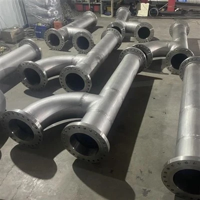
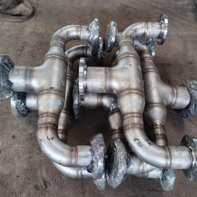
A reducer is a small fitting with an outsized job: it connects a larger pipe to a smaller one while the fluid keeps moving. Choose the wrong type - or install the right type in the wrong orientation - and a pump that should run for years can lose prime, vibrate, and erode its impeller, while a gravity drain line can fill with pooled liquid and settled solids.
This guide compares concentric and eccentric reducers across the dimensions that matter in real piping design: geometry, pump suction behavior, cavitation, gravity flow, hydraulics, standards, and materials.

Every section opens with a one-line conclusion you can quote directly, followed by the engineering rationale behind it. The rules apply to water, hydrocarbon, chemical, steam, and slurry lines designed to API, ASME, and Hydraulic Institute practice, and they hold regardless of material - carbon steel, stainless steel, or nickel alloy. We write them plainly enough for a student to follow and precisely enough for a practicing engineer to cite.
What Is the Difference Between a Concentric and an Eccentric Reducer?
A concentric reducer tapers symmetrically around a single centerline, like a cone; an eccentric reducer has one flat side, so the top (or bottom) of the large and small pipes line up while the two centerlines are offset. That single flat side is the whole point of the fitting: it lets the designer keep one edge of the line level and control where air or liquid collects.
Both fittings are made to the same dimensional standards, most commonly ASME B16.9 for butt-welding, with identical end diameters, wall thickness, and face-to-end lengths. They differ only in internal profile. A concentric reducer keeps the flow axis centered and symmetrical. An eccentric reducer is installed in one of two orientations: flat side up (FSU, also called top flat) or flat side down (FSD, also called bottom flat).
The practical consequence is simple. In a horizontal liquid line, a concentric reducer creates a high point at the top, where air and vapor can gather, and a low point at the bottom, where sediment can settle. An eccentric reducer removes one of those traps by keeping the opposite edge flush with the connecting pipe. Table 1 summarizes the differences.
Table 1. Concentric vs Eccentric Reducer: Key Difference
|
Attribute |
Concentric Reducer |
Eccentric Reducer |
|
Geometry |
Symmetrical cone, common centerline |
One flat side; centerlines offset |
|
Centerline |
Large and small ends aligned |
Offset; top or bottom edge flush |
|
Orientation choices |
None (single design) |
Flat side up (FSU) or flat side down (FSD) |
|
Horizontal pump suction |
Not recommended (vapor pocket risk) |
Required - flat side up (API 610 / ISO 13709) |
|
Gravity flow / drainage |
Not recommended (low-point pooling) |
Required - flat side down |
|
Pressure drop / turbulence |
Lowest; most symmetric velocity profile |
Slightly higher; asymmetric profile |
|
Air-pocket risk in horizontal liquid service |
High (high point at top) |
Eliminated on the flat side |
|
Best service |
Vertical runs, gas lines, discharge, headers |
Horizontal liquid lines needing vapor or drainage control |
Which Reducer Should You Use on a Horizontal Pump Suction Line?
Use an eccentric reducer installed flat side up (top flat). This is the layout required in API 610 / ISO 13709 centrifugal pump systems and the universal rule of pump suction piping, because it prevents air and vapor from pocketing at the high point of the reducer and being swept into the impeller.

Liquid entering a pump suction always carries some dissolved or entrained gas, and gas rises to the top of the pipe. With the flat side up, the top of the large and small pipes are flush, so gas travels with the flow toward the pump and leaves through the discharge. With a concentric reducer - or an eccentric reducer installed flat side down - a vapor pocket forms at the top of the transition. That pocket can detach and travel into the impeller, causing cavitation, flow disruption, loss of prime, and mechanical damage to the impeller, bearings, and seals.
API 610 / ISO 13709, the international standard for centrifugal pumps in petroleum, petrochemical, and natural gas service, directs the use of eccentric reducers in pump suction piping; industry guidance consistently states that if a reducer is used at the suction, it shall be eccentric, and it shall not be used to throttle flow. The 11th edition of API 610 corresponds to ISO 13709:2009, and the 12th edition was released in January 2021.
There are two exceptions worth memorizing. First, when the suction line drops vertically from above into the pump (supply from above), install the eccentric reducer flat side down so trapped gas can bleed back up the line toward the tank or header. Second, a vertical pump suction fed from overhead piping can use a concentric reducer, because there is no horizontal high point for vapor to collect in. In every case, place the reducer immediately at the pump suction flange rather than upstream with fittings between the reducer and the pump.
How Does Reducer Selection Prevent Cavitation and Protect the Pump?
Keeping vapor out of the pump preserves the Net Positive Suction Head Available (NPSHa) above the pump's required NPSHr; when that margin disappears, vapor bubbles form inside the impeller and collapse violently, eroding metal, shaking bearings, and destroying seals. The reducer's job at the suction is to keep the approach flow smooth and vapor-free so the available suction head is never wasted.
Cavitation, in plain terms: at the impeller inlet the liquid accelerates and its pressure drops. If the pressure falls below the liquid's vapor pressure, the liquid flashes into bubbles. As the bubbles move into higher-pressure zones they collapse with shock waves strong enough to pit impeller metal and excite vibration. The design requirement is that the available suction head (NPSHa) stays above the head the pump needs (NPSHr, read from the pump curve) by an adequate margin.
An air or vapor pocket at the suction behaves like lost suction head: it eats into the NPSH margin and triggers cavitation sooner. That is why orientation matters more than any other detail of the reducer. Suction layout guidance from the Hydraulic Institute (HI 9.6.6 and HI 9.8) and API RP 686 also stresses straight-run length: keep roughly 5 to 10 pipe diameters of straight suction pipe upstream of the flange - no elbows within about 5 diameters, no tees or valves immediately upstream - and locate the reducer at the flange itself. Keep suction velocities low (typically below about 1.5 m/s for water-like liquids) and never throttle the suction side.
When Should an Eccentric Reducer Be Installed Flat Side Down?
Install the flat side down when the line must drain completely or hold a constant bottom elevation: gravity flow lines, drainage and sewer runs, slurry and wastewater piping, steam lines carrying condensate, and horizontal pipe racks. The flat bottom keeps the invert level and stops liquid or solids from pooling inside the fitting.

In gravity flow, liquid runs along the bottom of the pipe, so the bottom profile is what matters. A concentric reducer - or an eccentric reducer with the flat side up - leaves a low pocket at the transition that never fully drains. In clean drainage lines that pocket holds stagnant water and promotes corrosion; in slurry and wastewater lines it lets solids settle, eventually blocking the line.
The same logic applies to steam lines that carry condensate. Condensate pooling in a low point can be picked up by the steam flow and slammed against fittings downstream, producing water hammer. Flat-side-down eccentric reducers keep the condensate moving and drainable. On pipe racks, the flat side down also maintains a constant bottom-of-pipe (BOP) elevation across the rack, so supports stay at one level.
Notice that this is the same fitting as in Section 2, rotated 180 degrees. The orientation is not a matter of preference: on a pump suction you fight vapor at the top, so the flat side goes up; on a gravity or drainage line you fight liquid and solids at the bottom, so the flat side goes down.
When Is a Concentric Reducer the Better Choice?
Choose a concentric reducer when the line is vertical, when the fluid is a gas, on pump discharge lines, on top-suction pumps fed from overhead, and anywhere symmetrical flow and minimum turbulence matter more than vapor or drainage control.
On vertical runs there is no horizontal high or low point, so the eccentric reducer's advantage disappears; gravity either helps the flow drain or does not create a vapor trap. A concentric reducer also loads supports and equipment nozzles symmetrically, avoiding the eccentric structural load an offset fitting can introduce. On horizontal gas lines there is no liquid to pool or drain, so the symmetric concentric profile is preferred.
Pump discharge lines are another standard concentric application: the suction-side vapor problem does not exist on the discharge, and the symmetric taper minimizes turbulence downstream of the pump. Layout guidance also calls for concentric reducers where overhead piping feeds a top-suction pump. Finally, concentric reducers are the default for instrument runs, headers, and every service where a uniform velocity profile protects measurement accuracy - and they are generally lower cost and more readily available than eccentric types. Just never let cost overrule reliability on a horizontal liquid suction.
Do Concentric and Eccentric Reducers Differ in Pressure Drop and Flow Performance?
In normal service the hydraulic difference is small - a short reducer's friction loss is minor next to valves, bends, and pipe length - but a concentric reducer produces the most symmetric velocity profile and the lowest turbulence, while an eccentric reducer's sloped side adds a slight asymmetry. Select the reducer to control vapor or drainage, not to save head.

Pressure drop through either fitting is a second-order effect. Reducers are short, and their loss coefficients are small compared with elbows, control valves, and the pipe run itself; no competent designer sizes a line on the reducer's K-factor alone. The meaningful difference is the velocity profile. The concentric reducer keeps the flow centered, so downstream flow is uniform. The eccentric reducer accelerates flow along its sloped side, producing a non-uniform profile.
That asymmetry has one well-documented consequence in pump suction service: a non-uniform approach flow can create unbalanced radial forces on the impeller, a consideration discussed in pump industry literature. In practice, the reliability benefit of the correct eccentric orientation at a suction far outweighs the small hydraulic penalty, and the concentric reducer's symmetry is a bonus on discharge and vertical lines where no vapor or drainage problem exists.
What Do the Standards Say - API 610, ASME B16.9, and the Hydraulic Institute?
The standards agree. API 610 / ISO 13709 directs eccentric reducers at pump suctions; ASME B16.9 defines the dimensional envelope for both concentric and eccentric butt-weld reducers; and Hydraulic Institute guidance (HI 9.6.6 / HI 9.8) and API RP 686 govern suction layout, including straight-run length. None of them recommends a concentric reducer on a horizontal pump suction.
API 610 / ISO 13709, Centrifugal Pumps for Petroleum, Petrochemical and Natural Gas Industries, is the reference for pump suction piping: reducers at the suction shall be eccentric, and the suction shall not be throttled. The 11th edition of API 610 is technically identical to ISO 13709:2009; the current 12th edition of API 610 was released in January 2021. ASME B16.9 covers factory-made wrought butt-welding fittings and gives the dimensions of both concentric and eccentric reducers; ASME B16.11 covers socket-weld and threaded versions, with MSS SP-75, EN 10253-2, and GB/T 12459 as regional or high-strength equivalents. Pressure ratings from 150# to 2500# align reducers with the connected piping.
For suction layout, Hydraulic Institute intake-design standards (HI 9.6.6 and HI 9.8) and API RP 686 set the practical rules: no elbows within about 5 pipe diameters of the suction flange, roughly 10 diameters of straight pipe upstream of disturbances, and a suction straight run typically around 5 diameters, with the reducer located at the flange. Table 2 collects the key references.
Table 2. Standards and Guidance Summary
|
Standard |
Scope |
Reducer-Relevant Requirement |
|
API 610 (11th ed.) / ISO 13709:2009 |
Centrifugal pumps for petroleum, petrochemical, and gas industries |
Eccentric reducers at pump suction; no suction throttling |
|
API 610 12th Edition (2021) |
Current edition of the centrifugal pump standard |
Same suction-piping intent; no longer references ISO 13709 numbering |
|
ASME B16.9 |
Factory-made wrought butt-welding fittings |
Dimensions for concentric and eccentric reducers |
|
ASME B16.11 / MSS SP-75 / EN 10253-2 / GB/T 12459 |
Socket-weld/threaded, high-strength, European and Chinese equivalents |
Same reducer types under alternate joining or regional standards |
|
HI 9.6.6 (Hydraulic Institute) |
Pump application and intake layout |
No elbows within ~5D of suction flange; ~10D straight upstream of disturbances |
|
HI 9.8 / ANSI/HI 9.8 |
Pump intake design |
Straight suction run for uniform approach flow |
|
API RP 686 |
Machinery installation and piping design |
Suction straight run typically ~5 pipe diameters |
Which Materials Are Available for Concentric and Eccentric Reducers?
Both reducer types are manufactured across the full range of stainless steels and nickel alloys - austenitic grades such as 304/304L, 316/316L, 317L, 321, 347, and 310S; duplex and super-duplex grades 2205 and 2507; and nickel alloys such as Alloy 825, Inconel 625, Monel 400, and Hastelloy C-276 - so the fitting can match the corrosion, temperature, and pressure duty of the line it joins.

Material selection follows the fluid, not the fitting type. Chloride concentration and temperature drive the first decision: 316L stainless covers moderate chloride service, duplex 2205 (PREN roughly 34) and super-duplex 2507 (PREN roughly 40 or higher) take over for seawater, offshore, and hot chloride service, with roughly double the yield strength of 316L.
Sour service with hydrogen sulfide, strong acids, and temperatures above about 500 degrees Celsius push the selection into nickel alloys - Alloy 825 for mixed acids and sour service, Inconel 625 for high-temperature strength and seawater, Monel 400 for hydrofluoric and marine environments, and Hastelloy C-276 for the most severe oxidizing and reducing media. Table 3 summarizes the common families.
Table 3. Reducer Materials and Typical Service
|
Material Group |
Example Grades |
Typical Service |
|
Austenitic stainless steel |
304/304L, 316/316L, 317L, 321, 347, 310S |
General chemical, water, steam, and mild corrosive service; 316L for chloride-bearing streams |
|
Duplex and super-duplex |
2205 (UNS S32205), 2507 (UNS S32750) |
Seawater, offshore, hot chloride service; about twice the yield strength of 316L; PREN 34-40+ |
|
Nickel alloys |
Alloy 825, Inconel 625, Monel 400, Hastelloy C-276 |
Sour gas (H2S), strong acids, high temperature, seawater, severe oxidizing and reducing media |
The dimensional standards in Section 7 apply identically to every material, so an eccentric reducer in Alloy 825 or super-duplex 2507 has the same face-to-end dimensions and pressure rating logic as one in 304 stainless. A dedicated stainless and nickel alloy manufacturer also verifies chemistry (PMI) and weld quality, which matters most exactly where the material was chosen for a demanding service.
How Do You Choose?
Answer four questions - (1) Is the line horizontal and liquid-full? (2) Is it a pump suction? (3) Must the line drain fully or hold a constant bottom elevation? (4) What is the corrosion and temperature duty? - then read the decision table below and verify the orientation on the isometric before fabrication.
Step 1: identify the service. Step 2: apply Table 4. Step 3: mark the orientation (FSU or FSD) on the drawing and the tag. Step 4: confirm the reducer sits at the pump suction flange with the required straight run upstream. Step 5: weld per procedure, apply non-destructive testing where the service demands it, and support the piping independently so no load transfers to the pump flange. Never throttle the suction side.
Checklist: Pump suction, horizontal, supply from below - eccentric, flat side up: prevents vapor pocket and cavitation (API 610).
- Pump suction supplied from above - eccentric, flat side down: lets gas bleed back up the line.
- Gravity flow, drainage, slurry, or steam condensate line - eccentric, flat side down: full drainage, no sediment, no water hammer.
- Vertical riser, gas line, pump discharge, or overhead-fed top suction - concentric: no vapor or drainage problem, best symmetry.
- Corrosive, sour, or high-temperature service - select the stainless or nickel alloy grade from Table 3 and specify PMI and NDT.
Table 4. Quick Selection Guide: Application to Reducer and Orientation
|
Application |
Reducer |
Orientation |
Why |
|
Pump suction, horizontal, supply from below |
Eccentric |
Flat side up |
Prevents vapor pocket and cavitation (API 610) |
|
Pump suction, supply from above (drop line) |
Eccentric |
Flat side down |
Lets trapped gas bleed back up the line |
|
Pump discharge |
Concentric |
- |
No vapor concern; symmetric flow |
|
Top-suction pump fed from overhead |
Concentric |
- |
Vertical approach; no high point |
|
Gravity flow / drainage line |
Eccentric |
Flat side down |
Full drainage; no sediment pooling |
|
Slurry / wastewater line |
Eccentric |
Flat side down |
Prevents solids settling and blockages |
|
Steam line with condensate |
Eccentric |
Flat side down |
Prevents condensate pooling and water hammer |
|
Vertical riser |
Concentric |
- |
Gravity assists; centered load on supports |
|
Horizontal gas line |
Concentric |
- |
No liquid to pool or drain |
The Bottom Line: One Rule of Thumb to Remember
Horizontal liquid line feeding a pump - eccentric, flat side up. Gravity or drainage line - eccentric, flat side down. Vertical, gas, or discharge line - a concentric reducer is fine. If you remember only one sentence, this is it.
The two reducer types exist for one reason: a horizontal liquid line has two failure modes, one at the top and one at the bottom, and each fitting handles one of them. An eccentric reducer manages both when oriented correctly - flat side up against vapor at a pump suction, flat side down against pooling in gravity flow. A concentric reducer earns its place wherever symmetry and simplicity beat vapor and drainage control.
Get the type and orientation right at the design stage and the fitting is invisible for decades; get it wrong and the pump or the drain tells you quickly. When in doubt, check the isometric, check the standard, and consult the manufacturer's dimension and material data for the exact grade and rating of your line.
References
[1] API 610 12th Edition - Guide to key changes (Amarinth Pumps)
[2] ISO 13709:2009, Centrifugal pumps for petroleum, petrochemical and natural gas industries (ISO Online Browsing Platform)
[3] API 610 (11th ed., ISO 13709) pump installation manual - suction reducer requirement (Changzhi Pump)
[4] EPCLAND - Piping layout engineering: eccentric reducers flat side up on pump suction
[5] EPCLAND - Concentric vs eccentric pipe reducers: engineering design and selection guide
[6] EnggCyclopedia - Use of eccentric reducer in pump suction piping (ANSI/HI 9.8 straight-run guidance)
[7] Flowmachinery - Prevent centrifugal pump cavitation (HI 9.6.6 suction rules)
[8] Industrial Monitor Direct - Pump suction piping: NPSH and cavitation (API RP 686 straight run)
[9] Project Materials - ASME B16.9 butt-weld fittings: reducer types and pump suction rule
[10] Piping Guide - Pump piping layout: eccentric on suction, concentric on discharge and top suction
[11] Pumps & Systems - Reducer fittings: eccentric profile and unbalanced radial force
[12] JN Alloy - How to use eccentric reducers: flat side up vs flat side down
[13] Huitong Pipe Fittings - Stainless steel vs duplex vs nickel alloy: PREN and chloride limits
[14] CHNMFY - Chemical pipeline alloy selection: duplex strength vs austenitic grades